Through-beam, retro-reflective and diffuse photoelectric sensors all detect objects without contact, but they differ in how the light path is arranged. Through-beam uses a separate emitter and receiver and gives the longest range and highest signal margin. Retro-reflective uses one housing plus a reflector. Diffuse detects light reflected by the target itself, needs only one device and no reflector, but is the most target- and background-dependent of the three.
Key Takeaways
- Mounting access decides first. If you can install devices on both sides of the detection point, through-beam is usually the most reliable choice. If only one side is accessible, choose retro-reflective or diffuse.
- Signal margin falls as the arrangement gets simpler. Through-beam offers the highest excess gain; diffuse offers the least and depends on target size, color and surface.
- The background is part of the application in diffuse mode. A shiny machine frame behind the target can be detected instead of the target. Background-suppression variants exist for exactly this problem.
- Speed is a system question, not only a sensor question. Response time, target length, gap length and conveyor speed must be checked together before counting small products.
- Special cases have dedicated answers. Transparent objects, tiny targets in tight spaces, and label or color-mark detection are covered by specialized sensor types and separate guides linked below.
How Each Sensing Mode Works
Through-beam (opposed mode)
A through-beam photoelectric sensor splits the light path into two separate devices: an emitter on one side of the detection point and a receiver on the other. The sensor switches when the target interrupts the beam. Because the receiver only has to see a strong, direct beam — not a weak reflection — this arrangement delivers the longest sensing ranges and the highest signal margin of the three modes. That margin is what makes through-beam tolerant of dust, lens contamination and misalignment drift over time.
The trade-offs are installation cost and access: two devices must be mounted, aligned and cabled, and both sides of the detection point must be physically reachable.
Retro-reflective (reflex mode)
A retro-reflective sensor houses the emitter and receiver together and aims both at a reflector mounted on the opposite side. The reflector returns the beam to the receiver; a target is detected when it blocks that return path. You get most of the reliability of a through-beam arrangement with wiring on only one side, plus simpler alignment than two separate devices.
The trade-offs: a reflector still has to be mounted opposite the sensor, and highly reflective targets can bounce enough light back to look like the reflector. Polarizing-filter variants exist to address exactly that failure mode — if the target is glossy film, foil or a shiny container, confirm the model uses polarization or another glare-rejection method.
Diffuse (proximity mode)
A diffuse sensor also combines emitter and receiver in one housing, but it detects light reflected directly off the target — no reflector, no second device. This is the simplest arrangement to install and the only one of the three that needs nothing on the far side of the target.
The trade-off is that detection now depends on the target itself. Light-colored, matte, large targets return more light than dark, glossy or small ones, so the effective sensing distance changes with the object. The background also matters: anything behind the target that reflects light — a conveyor frame, a wall, a machine panel — can produce a signal where the target should be. Two engineering answers exist for this:
- Background-suppression (BGS) variants evaluate the angle or position of the returning light instead of its intensity, so the sensor detects objects within a set distance window and ignores everything behind it. KJT Sensors lists a dedicated background suppression type within its photoelectric range.
- Distance-based (ToF) variants measure the time of flight of the light pulse and decide by distance rather than reflected intensity. KJT Sensors’ ToF laser photoelectric family is manufacturer-stated to detect at distances up to 3 m with switching frequency up to 1,000 Hz, largely independent of target color, shape and surface, including transparent objects and outdoor use.
Same-Dimension Selection Matrix
The matrix below compares the three arrangements on the dimensions that actually drive a selection decision. It is the working tool of this article — use it with the decision sequence in the next section.
| Decision dimension | Through-beam | Retro-reflective | Diffuse |
|---|---|---|---|
| Devices to mount | Emitter + receiver (2) | Sensor + reflector (2) | Single sensor (1) |
| Sides requiring access | Both sides | Both sides (reflector side only needs mechanical access) | One side |
| Wiring effort | Two cables | One cable | One cable |
| Typical range class | Longest of the three | Medium to long | Shortest of the three |
| Signal margin (excess gain) | Highest — tolerant of dust, contamination, misalignment | High | Lowest — depends on target reflectivity |
| Dependence on target color/surface | Very low | Low, except mirror-like targets (use polarized variants) | High — dark, glossy or small targets reduce effective range |
| Background influence | None (beam interruption) | None (beam interruption) | Significant — use BGS or ToF variants where background is close or reflective |
| Alignment effort | Highest (two-point optical alignment) | Moderate (sensor-to-reflector) | Lowest |
| Transparent-object capability | Best of the three when margin is high; confirm per model | Possible; polarized/CoVis-style variants help — confirm per model | Hardest case — use ToF or dedicated transparent-object variants; see the transparent-object guide |
| Best-fit situations | Long range, dirty air, critical counting, small objects crossing a beam | One-sided wiring with reflector access opposite, general presence detection | Compact machines, no far-side access, targets with consistent surface properties |
Range and frequency values are deliberately not stated per mode: they are model-specific. Confirm sensing distance, response time and switching frequency against the data sheet of the exact model before specifying.
A Four-Step Decision Sequence
Work through these questions in order; each answer narrows the field before the next question is asked.
Step 1 — What can you physically mount? If both sides of the detection point accept devices and cabling, through-beam is the default starting point because of its signal margin. If the far side can take a reflector but not a wired device, retro-reflective. If nothing can be mounted opposite the target, diffuse — and immediately plan how to handle the background.
Step 2 — What is the target? Note material, color, surface (matte or glossy), size and consistency. Opaque, consistent targets work with any mode. Dark, shiny, small or variable targets push you toward through-beam, or toward BGS/ToF diffuse variants. Transparent targets (PET bottles, film, glass) are a special case: KJT Sensors’ ToF family is manufacturer-stated to handle transparent objects, and the dedicated guide on detecting clear PET bottles and transparent film at high speed covers that decision in full.
Step 3 — What is the environment? Dust, mist, vibration, washdown and ambient light all consume signal margin. A mode that is marginal on a clean bench will fail in a dirty plant. Sunlight and strong industrial lighting are a distinct threat: modulated-light sensors reject constant ambient light, but direct sunlight can still saturate a receiver. Shading, sensor angle and optical filters are the standard countermeasures, and KJT Sensors positions its ToF family for outdoor use with resistance to sunlight interference (manufacturer-stated).
Step 4 — How fast is the line? This is where most selection errors surface. See the next section.
Counting Small Products: Is the Sensor Fast Enough? (S16)
For counting applications, the question is not “what is the sensor’s response time?” but “does the target block the beam long enough, and clear long enough, for the sensor and controller to register both events?” The method is general engineering practice:
- Measure the blocked time. Divide the target length (in the direction of travel) by the line speed. A 20 mm product at 1 m/s blocks the beam for about 20 ms.
- Measure the clear time. Divide the gap between products by the line speed. A 10 mm gap at 1 m/s clears the beam for about 10 ms.
- Compare both times against the complete signal chain. The sensor’s response time, the controller’s input filter and the PLC scan time all add delay. The shortest of the blocked/clear times must comfortably exceed the total chain delay — with margin for speed variation, product wobble and timing jitter.
- Check the sensor’s switching frequency rating. KJT Sensors’ ToF family, for example, is manufacturer-stated at up to 1,000 Hz switching frequency, which corresponds to millisecond-scale switching. Whether that is fast enough depends entirely on the times you calculated in steps 1–2.
- Leave engineering margin. If the calculation is tight, reduce the beam spot size, move the sensor to where products are better separated, or choose a faster variant — and verify with an on-site test at maximum line speed before committing to a quantity order.
If the products are very small or the installation space is tight, a fiber-optic arrangement often solves what a standard housing cannot; fiber-optic selection is covered in the dedicated guide.
Special Cases That Have Their Own Answers
Three common photoelectric requirements are deliberately not answered in depth here, because each is a full selection decision of its own:
- Labels and color marks. Detecting a label gap or a printed registration mark is a contrast-detection task with dedicated sensor types (label sensors, color-mark sensors). See the label-vs-color-mark comparison.
- Transparent objects at speed. See the clear-PET and transparent-film guide.
- Unstable or false signals after installation. If a correctly selected sensor still triggers falsely, the cause is usually optical (glare, background, contamination) or electrical (wiring, interference) — the photoelectric false-signal troubleshooting guide works through the diagnosis.
KJT Sensors Product Families by Arrangement
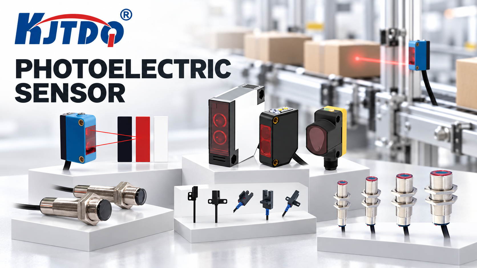
KJT Sensors’ photoelectric portfolio, as listed on its photoelectric product page, covers all three arrangements plus the specialized variants discussed above:
- Standard and laser photoelectric series — general through-beam, retro-reflective and diffuse detection; laser variants for small spots and precise positioning.
- Background suppression type — diffuse detection with a defined distance window, for targets in front of close or reflective backgrounds.
- ToF laser photoelectric sensors — distance-based detection manufacturer-stated up to 3 m and up to 1,000 Hz, positioned for transparent objects, complex backgrounds, high-speed lines and outdoor use.
- Optical fiber and fiber amplifier series — small targets and confined mounting spaces.
- Slot-type series — fork-style through-beam arrangements for edge, label and small-part detection without alignment work.
- Label sensors and color-mark/color sensors — dedicated contrast detection for labeling, printing and packaging webs.
- Square series, analog series and explosion-proof photoelectric variants — form-factor, measurement-output and hazardous-area requirements respectively. Explosion-proof selection is a compliance decision and must be based on model-level certificates.
Browse the full range on the KJT Sensors photoelectric sensor page or the product center. For the broader target-material question — when photoelectric sensing is the wrong principle entirely — see the object-detection selection guide.
Limitations and Unsuitable Conditions
- This comparison covers presence and counting detection. It does not cover precision distance measurement, which belongs to measuring-class sensors.
- No sensing distance, response time or frequency value in this article should be applied to a specific model; all such figures are model-specific and must come from the model’s data sheet. The ToF figures quoted (up to 3 m, up to 1,000 Hz) are manufacturer-stated page values for that family, verified 2026-10-09, and are not a guarantee for any individual model.
- Highly reflective targets in retro-reflective mode, and transparent targets in any mode, require variant-level confirmation — ideally with sample testing — before specification.
- Safety-related detection (personnel protection) requires safety-rated devices such as safety light curtains with model-level certification; standard photoelectric sensors must not be substituted for safety functions.
Frequently Asked Questions
Which photoelectric mode is best when both sides of the target are accessible? Through-beam is usually the first choice when both sides can be mounted and cabled, because its separate emitter and receiver deliver the longest range and the highest signal margin. That margin buys tolerance against dust, contamination and alignment drift. Choose retro-reflective instead when cabling the far side is impractical but a reflector can be mounted there.
When should I use a reflector instead of a separate receiver? Use retro-reflective when you want through-beam-like reliability but can only wire one side. The reflector needs only mechanical access for mounting and occasional cleaning. Watch for mirror-like targets, which can mimic the reflector’s return signal — polarized variants address that failure mode.
When does the background become a problem in diffuse sensing? Whenever the surface behind the target reflects light toward the receiver — conveyor frames, machine panels, walls — and sits within the sensor’s detection range. If you cannot remove or darken the background, specify a background-suppression or ToF (distance-based) variant, which decides by position or distance rather than by reflected intensity.
Can a diffuse sensor detect transparent film or bottles? Standard diffuse sensors are the weakest choice for transparent targets because little light returns from the target itself. Distance-based ToF variants are the stronger option — KJT Sensors states transparent-object capability for its ToF family — and very thin or fast transparent webs are covered in the dedicated transparent-object guide.
How do I know whether a sensor is fast enough to count my products? Calculate the blocked time (product length ÷ line speed) and the clear time (gap ÷ line speed). Both must comfortably exceed the total delay of the sensor response plus the controller input filter and PLC scan time. Then confirm the sensor’s switching-frequency rating covers the required event rate, and verify by test at maximum line speed.
What information should I send a manufacturer to get the right mode and model recommended? Target material, color, transparency and size; mounting access on both sides; required sensing distance; line speed and product spacing; ambient light, dust and washdown conditions; and the required output type. Photos of the detection point and samples of difficult targets (transparent, glossy, very dark) substantially improve recommendation quality.
Conclusion
The three photoelectric arrangements are not three grades of the same product — they are three answers to three different installation geometries. Through-beam buys maximum reliability at the cost of two-sided mounting; retro-reflective trades a reflector for single-side wiring; diffuse minimizes installation at the price of target- and background-dependence, which BGS and ToF variants are designed to recover. Decide mounting access first, then qualify the target and environment, then prove the speed with a blocked-time/clear-time calculation and an on-site test.
Ready to specify a photoelectric sensor? Send KJT Sensors your target details, mounting constraints and line speed — the application team will recommend a mode and model, and can arrange sample testing for difficult targets. Browse the photoelectric range or start from the product center.
Sources
| # | Source | Type | Used for |
|---|---|---|---|
| 1 | KJT Sensors photoelectric sensor category page — https://www.kjt-sensors.com/list-photoelectric.html (verified 2026-10-09) | KJT Sensors first-party | Product family coverage: standard, laser, slot-type, analog, fiber amplifier, optical fiber, background suppression, square, color-mark, label, safety light curtain, explosion-proof, ToF variants |
| 2 | KJT Sensors ToF laser photoelectric sensor page — https://www.kjt-sensors.com/list-tof_laser_photoelectric_sensor.html (verified 2026-10-09) | KJT Sensors first-party | ToF family statements: up to 3 m, up to 1,000 Hz, transparent-object and outdoor positioning, color/shape/surface independence (all manufacturer-stated) |
| 3 | KJT Sensors product center — https://www.kjt-sensors.com/list-product.html (verified 2026-10-09) | KJT Sensors first-party | Portfolio navigation |
| 4 | KJT Sensors Photoelectric Sensor Category Knowledge Base (internal, 2026) | KJT Sensors internal documentation | ToF, fiber-optic, label and color-mark product detail; selection-recommendation structure; application and pain-point context |
https://www.kjt-sensors.com/
KJT Sensors