One series, two current ratings, two crimp contacts — and a pitch shared by two connector systems that do not mate.
Most engineers meet the JST ACH the same way: through a requirement they cannot quite meet anywhere else.
You need 2 amps. The board is tight. The connector has to be small. You look at the usual 1.0mm and 1.25mm parts and they stop at 1A to 1.5A. Then you find a 1.2mm pitch connector rated at 2A, and it looks like the answer.
It is the answer — for some designs. For others it is a specification trap, because that 2A figure is not a single number, and the same series contains a second trap that costs people real money: the 1.2mm pitch is shared with a connector that does not mate with it.
Here is the whole thing, with every figure traced to JST’s own published ACH documentation or to KONNRA’s published KR1201 documentation — and the places where the two disagree flagged rather than averaged.
What the ACH actually is
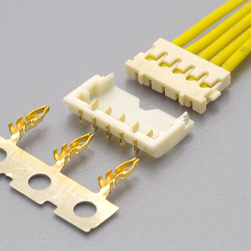
The JST ACH (also written ACH1.2) is a 1.2mm pitch, single-row, disconnectable crimp-style wire-to-board connector:
- Pitch: 1.2mm, single row
- Body: 1.4mm high, 4.3mm wide
- Circuits: 1 to 5
- Current rating: 2A AC/DC for 1–3 circuits, 1.5A AC/DC for 4–5 circuits, both at AWG #28
- Voltage rating: 50V AC/DC
- Operating temperature: −25°C to +85°C, including temperature rise from current flow
- Applicable wire: AWG #32 to #28, insulation O.D. 0.38 to 0.63mm
- Contact resistance: 10mΩ max initial, 20mΩ max after environmental tests
- Insulation resistance: 100MΩ min
- Withstanding voltage: 500 VAC per minute
- Housing: PBT, UL94V-0, natural (white)
- Contact: copper alloy, nickel-undercoated, gold-plated
- Standards: UL Recognized E60389 · CSA Certified LR20812 · RoHS
- Construction: top entry but side feed — socket mates vertically, wires exit horizontally
- Cross-reference equivalent: KONNRA KR1201
JST’s own description is unusually direct about why the series exists: it “was originally designed for a DC power supply application.” This is not a general-purpose signal connector that happens to carry current well. It is a power connector designed to stay small.
The 2A rating is two ratings
This is the single most misquoted thing about the series.
JST’s current rating for the ACH is circuit-count dependent:
- 1 to 3 circuits → 2A AC/DC
- 4 to 5 circuits → 1.5A AC/DC
Both quoted at AWG #28.
Read that again as a designer: a five-circuit ACH is rated 1.5A, not 2A. A datasheet, a distributor listing or a cross-reference table that says “2A” without the circuit count is quoting the 1–3 circuit figure. A 5-circuit design built to it has no margin at all — and it will not fail on the bench, it will fail in the field, or in qualification, or in a customer’s thermal test.
Then there is the second-source wrinkle. The KONNRA KR1201 is documented at 1.5A flat — which is exactly JST’s 4–5 circuit figure. That produces two opposite situations depending on your design:
- 1–3 circuits: the published KR1201 figure understates the original part’s capability by 25%. That is not a statement that the connector cannot carry 2A — it is a statement of what has been documented. If you need 2A on three circuits or fewer, ask for the rating to be confirmed against your circuit count in writing.
- 4–5 circuits: the figures match, and there is no derating question to resolve.
Why 2A at 1.2mm is worth having at all. In the 1.0mm–1.5mm band, almost everything else is 1A or 1.5A: Molex’s Pico-EZmate at 1.20mm is 1.5A, JST’s own SH at 1.00mm is 1A. If your requirement is 2A on three circuits or fewer, the ACH is one of the few connectors that meets it without going up a pitch — and on a dense board, staying at 1.2mm is usually worth more than the headroom.
“Top entry but side feed” — what the construction buys you
JST describes the ACH as “top entry but side feed type.” It reads like marketing; it is actually the engineering reason to specify this connector.
- Top entry — the socket mates onto the header from the vertical direction. No board-edge access, no sliding sideways, so the connector can sit in the middle of a board.
- Side feed — the wires leave the socket horizontally.
Put together: the harness exits parallel to the board. That sounds like a small thing until you do the geometry. A vertical wire exit adds the cable’s bend radius to the height of the assembly — which on a 1.4mm-tall connector completely defeats the reason you chose a 1.4mm-tall connector. With a side feed, the clearance problem moves from the vertical axis to the horizontal one, and on thin devices the horizontal axis is usually the one you have.
Three consequences that show up in real designs:
- The 1.4mm body height is usable, not theoretical. The cable does not consume it.
- Strain relief can be anchored to the board. A horizontal run can be tied down a few millimetres from the connector; a vertical run over a low connector usually cannot.
- The harness can be serviced without lifting it over the connector. Unmating is a vertical pull on the socket while the harness stays flat.
JST also builds in a feature most 1.2mm connectors lack: “a sucking area on bottom of inside header is available.” That flat pad on the inside bottom is sized for a pick-and-place nozzle, which is why the ACH can go through a standard SMT line rather than being hand-placed. The header is supplied on embossed tape.
One thing to check on the drawing: the offset between the header’s board pattern and the socket’s wire-exit direction defines which way the harness runs. On a layout with limited horizontal clearance, confirm the exit direction against your enclosure before you commit the footprint.
Two crimp contacts, and an overlap that runs the wrong way
JST splits the ACH’s wire window across two crimp contacts rather than one. Picking the wrong one is the most common ACH harness error — and the reason is counterintuitive.
- SACH-003G-P0.2 — AWG #30 to #28 (0.05–0.08mm²), insulation O.D. 0.5 to 0.63mm, 30,000 per reel
- SACH-003G-P0.2B — AWG #32 to #30 (0.032–0.05mm²), insulation O.D. 0.38 to 0.5mm, 30,000 per reel
Both contacts cover AWG #30. So in the #30 band, the conductor gauge does not decide between them — the insulation outside diameter does:
- Insulation 0.5mm and above →
SACH-003G-P0.2 - Insulation below 0.5mm →
SACH-003G-P0.2B
On a 1.2mm pitch, where the crimp barrel has almost no room, that distinction is the difference between a reliable crimp and a rejected harness.
And the series figure is just the union of the two. JST quotes the ACH as accepting AWG #32 to #28 with insulation of 0.38 to 0.63mm — which is precisely the two contacts’ windows joined together. If your BOM says “AWG #32–28” without naming the contact, it has not yet specified the part.

A related note on wire selection. JST quotes both current ratings — 2A and 1.5A — specifically at AWG #28. The series accepts wire down to AWG #32, but the current figure is not quoted at that gauge on the same line. If your harness uses #30 or #32 and you are close to the rating, confirm the applicable figure for your gauge rather than carrying the AWG #28 number across.
Circuit counts, and the arithmetic that catches drawing errors
JST documents the ACH in 1, 2, 3, 4 and 5 circuits, and the body grows by exactly 1.2mm per circuit:
- 1 circuit — B dimension 1.6mm
- 2 circuits — A dimension 1.2mm, B dimension 2.6mm
- 3 circuits — A dimension 2.4mm, B dimension 3.8mm
- 4 circuits — A dimension 3.6mm, B dimension 5.0mm
- 5 circuits — A dimension 4.8mm, B dimension 6.2mm
The A dimension follows A = (circuits − 1) × 1.2mm — which is the cross-check to run against any drawing you are handed. If the arithmetic does not come out, something on the drawing is wrong, and it is worth finding out which before you release it.
Two differences against the KONNRA documentation:
- KONNRA states 2 ~ 7P, where JST documents 1 to 5. That is up to two positions beyond the original’s range.
- The single-circuit option is not covered. If your design is a 1-circuit ACH, the KR1201 documentation does not describe it.
Confirm the exact count you intend to order rather than assuming the ranges are equivalent.
The most expensive mistake: 1.2mm is not one connector
If you remember one warning from this article, make it this one.
The JST ACH and the Molex Pico-EZmate are both 1.20mm pitch. They are different connector systems with different housings and different headers, and they do not mate.
KONNRA cross-references them as KR1201 (ACH) and KR1200 (Pico-EZmate) — two different parts for the same pitch. This is the single most common ACH sourcing error, and it usually surfaces late, after a footprint has been committed.
Two related traps:
Do not compare the ACH’s 1.4mm to the Pico-EZmate’s 1.55mm directly. The ACH figure is a body height; the Pico-EZmate figure is a mated height measured from the PCB. Those are different measurements of different things. Compare mated height to mated height, and body height to body height.
And if 2A is not enough, look before you assume you need a bigger connector. Molex’s Pico-EZmate Plus reaches 2.8A at 1.00mm pitch — higher current at a smaller pitch than the ACH, achieved with a different contact system and mating design.
For context on where the ACH sits in the family: JST SH is 1.00mm / 1A, JST GH is 1.25mm / 1A, JST ZH is 1.50mm / 1A, JST PH is 2.00mm / 2A at 100V, and JST XH is 2.50mm / 3A at 250V. The ACH’s position — 2A at 1.2mm — is genuinely a gap-filler, not just another pitch option.
Cross-referencing to the KONNRA KR1201
The KR1201 is documented as KONNRA’s equivalent to the ACH, specified at component level — a housing, a right-angle wafer and a crimp terminal — covering the wire-to-board path.
Where the two documents agree is worth stating explicitly, because on a cross-reference it is not a given: the pitch, the single-row configuration, the 1.4mm × 4.3mm body, the 50V rating, the 100MΩ minimum insulation resistance, and the 500 VAC per minute withstanding voltage. On this series, those line up — including the withstanding voltage, which is a row that often does not.

Where they differ. Nine points, in the order they tend to bite:
- Current rating — flat versus circuit-count dependent. JST: 2A (1–3 circuits) / 1.5A (4–5). KONNRA: 1.5A flat. As covered above, a 1–3 circuit design is understated by 25% and a 4–5 circuit design matches. State your circuit count and current on the enquiry.
- Circuit counts — 1 to 5 versus 2 ~ 7P. Wider at the top, and the single-circuit option JST offers is not covered.
- Insulation outside diameter — a two-sided window versus a maximum only. JST specifies 0.38 to 0.63mm; KONNRA documents 0.75mm max with no published minimum. On a 1.2mm pitch the acceptable band matters in both directions: a wire below 0.38mm O.D. is outside JST’s specification, and the KR1201 documentation gives no lower bound at all. Ask for the minimum, for the terminal you intend to order.
- Contact resistance on different bases. JST: 10mΩ max initial and 20mΩ max after environmental tests. KONNRA: 20mΩ max — which is JST’s after-environmental-test figure, not its initial value. This is not KONNRA being looser; it is a different measurement basis. Compare initial to initial.
- Operating temperature. JST: −25°C to +85°C, and JST states the range includes the temperature rise caused by current flow — a stricter definition than a bare ambient range. KONNRA: −40°C to +105°C. If you rely on operation above +85°C or below −25°C, ask for the supporting test data rather than taking the wider figure at face value.
- Housing material. JST specifies PBT, UL94V-0, natural (white); KONNRA documents PA66 / LCP. Different polymer families, with different moisture absorption and dimensional behaviour. If your process window or your customer’s specification names a material, confirm equivalence.
- Standards. JST lists UL Recognized E60389 and CSA Certified LR20812. KONNRA’s product documentation states RoHS compliance, with UL certification asserted at brand level. If your qualification requires UL Recognized component status specifically for this part, ask for the file reference.
- Gold thickness is stated by neither side. JST describes the contact as “copper alloy, nickel-undercoated, gold-plated”; KONNRA describes it as “gold flash over nickel”. Both are gold over a nickel undercoat, in the same sequence — so this is often misread as a difference when it is not. What is true is that neither document gives a thickness in microns. If your qualification specifies a gold layer thickness, ask for the figure; do not infer it from the word “flash”.
- Crimp tooling documented by JST, not by KONNRA. JST publishes the crimp machine (
MKS-L-10-3,AP-K2N MKS-L-10-3) and the applicator (MK/SACH-003-02, withAPLMK SACH003-02as the applicator-with-dies option). KONNRA does not document tooling against the KR1201 terminal. If you crimp in-house, ask which applicator the terminal is validated against — and note that the machine and the applicator are two separate part numbers, so ordering by applicator alone can leave a line stalled.
One scope note: JST also publishes ACH documentation for a wire-to-wire version of the series, at the same 2A and 50V headline ratings. KONNRA’s published KR1201 covers the wire-to-board path. A wire-to-wire requirement needs separate confirmation.

The pre-release checklist
Run this before releasing a drawing for anything in the ACH family.
- Pitch measured, not assumed. 1.2mm is JST ACH or Molex Pico-EZmate. 1.25mm is JST GH or Molex PicoBlade. 1.00mm is JST SH. None of them mate.
- Current rating checked against your circuit count — 2A at 1–3 circuits, 1.5A at 4–5. Not a single family number.
- Circuit count confirmed — JST documents 1 to 5; the KR1201 range is stated as 2~7P, and the single-circuit option is not covered.
- The correct crimp contact selected —
SACH-003G-P0.2for AWG #30–28 at 0.5–0.63mm insulation;SACH-003G-P0.2Bfor AWG #32–30 at 0.38–0.5mm. In the AWG #30 band, insulation diameter decides, not conductor gauge. - Insulation outside diameter inside 0.38–0.63mm — and note the KR1201 documentation publishes only a 0.75mm maximum, with no minimum.
- Contact resistance compared on the same basis — initial to initial, after-environmental-test to after-environmental-test.
- Operating temperature judged against the right definition — JST’s range includes temperature rise from current flow.
- Wafer geometry and wire-exit direction matched to your layout, including which way the harness leaves the board.
- Body height and width checked against the enclosure — 1.4mm high, growing 1.2mm per circuit.
- Housing material confirmed against your process or customer requirement — PBT UL94V-0 versus PA66 / LCP.
- UL Recognized status confirmed if your qualification names it — JST cites E60389 and CSA LR20812.
- Crimp machine and applicator identified together if you crimp in-house.
- Gold thickness confirmed in microns if your specification names one — neither document states it.
- Wire-to-board or wire-to-wire confirmed — the KR1201 documentation covers the wire-to-board path.
Getting a cross-reference check
Most ACH enquiries stall on the same thing: the buyer is not sure what information the supplier needs, so the enquiry never gets sent. The list is short:
- The original part number if you have it — socket
ACHR-…V-S, headerBM…B-ACHSS-GAN-TF, or contactSACH-003G-P0.2 - Circuit count — the rating changes at four circuits
- Your load current, so the 2A-versus-1.5A question is settled for your design
- Wire gauge and insulation outside diameter — the window is split across two contacts
- Connector only, or a finished harness (and if a harness, length and far-end termination)
- Wafer geometry and wire-exit direction
- Application and annual volume
- A drawing or photo if the part number is unreadable
Four things then get confirmed against JST’s own documentation: the current rating for your circuit count, the crimp contact that matches your wire and insulation, the wafer geometry and exit direction, and the insulation diameter window. Those four are where an ACH cross-reference most often goes wrong.
Connector lead time is typically 2–3 weeks, wiring harness lead time typically 3–4 weeks, and complete connector set samples can be delivered within 45 days.
Full technical write-up: JST ACH 1.2 Connector Complete Guide
Disclosure: I work with KONNRA, which manufactures the KR1201 cross-reference to the JST ACH. The JST figures in this article are taken from JST’s own published ACH series documentation; the KONNRA figures are from KONNRA’s published KR1201 documentation. Where the two disagree, I have flagged the difference rather than averaged it — and where a parameter is not stated in either document, I have said so instead of filling the gap.
https://konnra.com/jst-ach-1-2-connector-complete-guide/
Dongguan Konnra Electronics Co., Ltd