Polyurethane Lined Flowmeter Electrode Fouling: 5 Checks
Direct answer: Yes — in some applications, deposits forming on the measuring electrodes can interfere with signal pickup and produce readings that drift, spike or fail to repeat, even when the polyurethane liner itself looks completely intact. But electrode fouling is only one of several possible causes of an unstable signal. A liner that passes a visual inspection tells you almost nothing about whether the electrodes are clean, whether the tube is full, whether the grounding is sound, or whether the liquid’s conductivity is adequate for the sensor. Unstable readings have to be diagnosed as a system, not attributed to a single component.
How Electrode Fouling Affects the Measurement Signal
An electromagnetic flowmeter has two jobs that are handled by two different parts of the sensor, and confusing them is the source of most misdiagnosis.
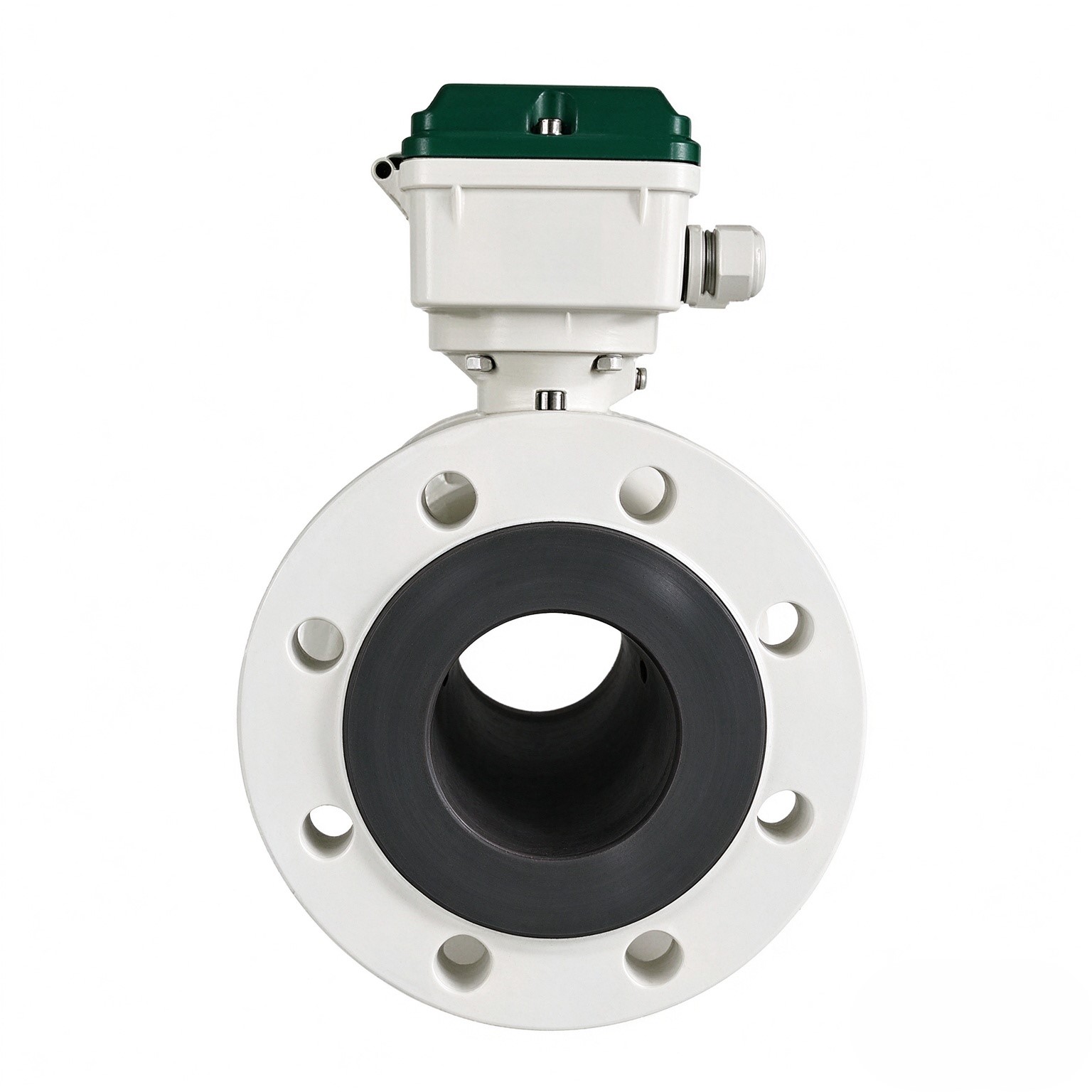
The liner is the insulator. Its role is electrical, not mechanical. It lines the inside of the measuring tube so that the induced signal is forced to travel through the liquid and reach the electrodes instead of short-circuiting through the metal pipe wall. A polyurethane liner that is not cut, blistered or delaminated is still doing that insulating job.
The electrodes are the signal path. They are small wetted contacts that pick up the very low-level voltage generated as conductive liquid moves through the magnetic field. That signal is small to begin with, and the interface between electrode surface and liquid is where it is collected.
When a coating forms on the electrode face — a film of scale, oil, grease, biofilm, polymer residue, pigment, or a chemical precipitate — the electrical contact between the metal and the flowing liquid is altered. The consequences depend on what the deposit is:
- A thin, conductive film may shift the reading by a small but repeatable offset.
- An insulating film can weaken the signal, making the reading drop toward zero while flow continues.
- An uneven or partially attached deposit can make the signal intermittent, so the reading jumps, drifts or fails to settle.
- Deposits that build up and shed irregularly produce exactly the kind of wandering output that gets blamed on the liner.
So the liner can be perfect and the reading still wrong. Conversely, the reading being wrong does not prove the electrodes are fouled. That distinction is the whole point of a structured diagnosis.
Other Possible Causes of an Unstable Reading
Before concluding that deposits are responsible, rule out the factors that produce the same symptoms.
Inadequate liquid conductivity. Electromagnetic flowmeters need a minimum conductivity to generate a usable signal, and that threshold depends on the sensor design and the cable length. Low-conductivity liquids — deionised water, some solvents, certain food products — can produce a noisy or drifting output with clean electrodes and a perfect liner. If the conductivity of the actual process liquid is unknown, it is worth establishing rather than assuming.
An incompletely filled measuring tube. Partial filling is one of the most common reasons for instability, and it is frequently intermittent. Entrained air, a downward-sloping installation, a pump pulling air, or a partially open valve upstream can all cause the tube to run partly empty. The signal becomes erratic in a pattern that tracks the process, not the sensor.
Grounding and bonding problems. The flow signal is measured relative to the liquid, so the sensor grounding has to be correct and the pipe flanges properly bonded. Missing, corroded or high-resistance ground connections, or stray currents travelling through the pipework, produce noise that mimics a failing sensor.
Electrical interference. Variable-frequency drives, welding equipment, large motors and poorly routed signal cables can all couple noise into the measurement circuit. Shielded, properly separated cable runs and correct screen termination matter more in electrically noisy plants than in clean ones.
Unsuitable process conditions. Slurries with high solids content, pulsating flow from reciprocating pumps, two-phase flow, and rapid temperature swings all put the measurement outside the conditions a standard sensor was configured for. Polyurethane is chosen for abrasion resistance, but abrasion resistance and signal stability are separate questions.
Deposits elsewhere in the flow path. A coating on the pipe wall or on the grounding electrodes changes the electrical environment just as effectively as a coating on the measuring electrodes.
None of these explains every unstable reading, and neither does fouling. The value of a diagnosis is in eliminating them one at a time.
A Practical Troubleshooting Sequence
Work through these steps in order. Each one either removes a candidate cause or tells you what to investigate next.
-
Confirm the actual process conditions. Establish what is flowing, at what temperature, at what concentration, and whether the medium has changed since commissioning. A new additive, a different supplier’s product or a change in cleaning regime can introduce a deposit that did not exist before. Compare current behaviour against the conditions the meter was configured for.
-
Check whether the pipe is genuinely full. Verify that the sensor is installed where the tube runs full under all operating states, including low-flow and pump-stop conditions. Look for air entrainment upstream, and check that valves are not creating partial-empty conditions. If the instability disappears when the line is run at high flow and returns at low flow, filling is a strong suspect.
-
Review conductivity if it is known — or find out. Obtain the conductivity of the actual medium at process temperature. If it sits near the lower limit for the sensor, that alone may explain the noise. This is a specification question, not a fault.
-
Inspect grounding and wiring. Check the grounding arrangement, the condition of grounding straps and flanges, and the integrity of signal cable screens. Confirm wiring matches the manufacturer’s diagram for the specific converter and sensor pairing. Loose terminals and corroded joints cause intermittent faults that look exactly like a failing electrode.
-
Follow the manufacturer’s procedure for electrode inspection or cleaning. Do not open the sensor, remove it from the line, or clean the electrodes using a method of your own devising. Ask the supplier for the inspection and cleaning procedure that applies to your exact sensor build, wetted materials and process medium, and follow it. Kaifeng Xinya Instrument Co., Ltd. can advise on configuration-specific checks for the supplied sensor, including what the electrodes are made of and which cleaning approaches are compatible with the liner and electrode materials in that build.
Record what you observe at each step. A drift that correlates with a process change points somewhere different from a drift that appears at a fixed time each day, and the difference is often the fastest route to the answer.
Cleaning and Inspection: Confirm Before You Act
Cleaning an electrode is not a default action. The correct method depends on the electrode material, the liner material, the deposit chemistry and the process itself, and a method that works on one installation can damage another.
- Confirm with the sensor supplier which cleaning agents and mechanical methods are approved for your specific build before anything touches the wetted parts.
- Aggressive solvents, acids, alkalis or abrasives chosen by guesswork can attack the electrode surface or the polyurethane liner, turning a recoverable signal problem into permanent damage.
- Never assume that fouling is the diagnosis simply because cleaning appeared to help once. A reading that improves temporarily and then degrades again is telling you the deposit is being formed continuously — which is a process or materials question, not a maintenance interval.
- Do not adjust electrical settings, damping, or calibration constants to mask an unstable signal. Masking noise in the electronics leaves the underlying cause in place and makes the next diagnosis harder.
FAQs
Can a clean liner guarantee stable readings?
No. The liner’s job is electrical insulation of the measuring tube, and an undamaged liner only tells you that one failure mode is absent. Stable readings also require clean electrodes, adequate liquid conductivity, a full tube, correct grounding and a reasonable electrical environment. A clean liner is a necessary condition in many installations, not a sufficient one.
Does every signal fluctuation mean the liner is worn?
No, and reaching that conclusion early is expensive. Fluctuation can come from electrode deposits, low conductivity, partial filling, grounding faults, electrical interference, pulsating flow or entrained air. Liner damage is one candidate among several, and it should be the conclusion of a diagnosis rather than its starting assumption.
Should electrodes be cleaned using any available chemical?
No. Cleaning agents and mechanical methods have to be approved for the exact sensor, electrode material, liner material and process medium involved. An unsuitable chemical can corrode the electrode, degrade the polyurethane liner, or leave residue that is unacceptable in hygienic service. Obtain the approved procedure from the sensor manufacturer first.
Getting Configuration-Specific Guidance
Electrode fouling is a real and common cause of unstable electromagnetic flowmeter readings, but it is not the only one, and it cannot be confirmed by looking at the liner. Confirm the process conditions, check that the tube is full, establish the conductivity, verify grounding and wiring, and then follow the manufacturer’s approved inspection procedure for your exact sensor.
For sensors supplied by Kaifeng Xinya Instrument Co., Ltd., configuration-specific troubleshooting guidance — covering electrode and liner materials, compatible cleaning approaches and appropriate diagnostic checks for the installed build — is available from the supplier so that maintenance decisions are based on the actual sensor specification rather than on general assumptions.
https://www.sytcflowmeter.com/
Kaifeng Xinya Instrument Co., Ltd.