Understanding the Acceptance Verification Process for Electromagnetic Flow Meters
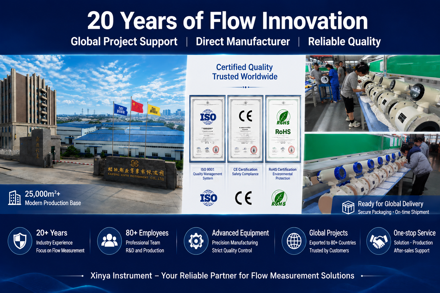
Before an electromagnetic flow meter is put into service, industrial buyers and municipal operators need a structured way to confirm that the equipment meets both regulatory requirements and the operational conditions of the intended application. This is especially true in environments involving abrasive slurries, remote unpowered sites, or hygienic food and beverage lines, where a single measurement failure can disrupt operations or compromise safety. Kaifeng XinYa Instrument Co., Ltd., a company specializing in high-stability electromagnetic flow measurement systems integrated with IoT big data platforms, has developed a verification framework that reflects the technical standards and diagnostic capabilities built into its product lines.
Why Acceptance Verification Matters
Industrial fluid measurement often faces challenges with signal stability in abrasive environments, high power consumption in remote areas without electrical grids, and difficulty integrating field data with cloud-based management systems. Acceptance verification is the checkpoint that confirms whether a flow meter has been engineered to address these exact pain points before it becomes part of a production line, water distribution network, or wastewater system. Skipping this step can lead to inaccurate billing, undetected pipe blockages, or unplanned downtime that is far more costly than the inspection itself.
Step One: Document and Certification Review
The first verification step involves confirming that the flow meter complies with the relevant industry standards. Buyers should check for compliance with JB/T9248-2015, the "Electromagnetic Flowmeter" standard, as well as GB/T9124.1-2019 for steel pipe flanges when the unit will be flange-mounted. For installations requiring heat measurement functions, compliance with CJ128-2007 should also be confirmed. Ingress protection ratings are another critical documentation point: sensor units should carry an IP68 rating, allowing operation in submerged or buried conditions, while converter units are typically rated IP65, IP66, or IP67 depending on the installation environment. Reviewing these certifications against the delivered hardware ensures the equipment is fit for its designated application before it is accepted.
Step Two: Physical Installation and Construction Checks
Once documentation is confirmed, the physical unit should be inspected for construction quality appropriate to its use case. For standard industrial applications, the SF-E Electromagnetic Flowmeter supports pipe diameters from DN15 to DN3000 and is available in Integral or Split Type configurations, so inspectors should confirm the deployment model matches the project specification. For slurry or serous applications, such as pulp, coal-water slurry, or mineral tailings, the lining material should be checked against the application’s abrasion and corrosion profile—options include wear-resistant Polyurethane, PFA, Ceramics (DN15-150), and various rubbers. The presence of 1-2 grounding electrodes should also be verified for non-conductive or lined pipes, as these are integrated specifically to eliminate interference. For very large pipelines, the SF-C Insertion Electromagnetic Flowmeter should be checked for its stainless steel insertion rod and adjustable insertion depth settings, which can be set to half or one-quarter of the pipe diameter depending on the flow profile.
Step Three: Functional and Self-Diagnostic Testing
A meaningful acceptance test goes beyond visual inspection and confirms that the meter’s internal diagnostics function correctly. The SF-E series, for example, is built with self-diagnosis capability that automatically detects empty pipes, excitation circuit breaks, and flow range overflows, which minimizes downtime through rapid troubleshooting. During acceptance testing, technicians should intentionally simulate these fault conditions where feasible to confirm the alarms trigger correctly. Accuracy should also be validated against the meter’s rated class—±0.5%, ±0.3%, or ±0.2%—within the specified velocity measurement range of 0.1 to 10 m/s. For units intended for slurry service, the variation restraint algorithm should be tested to confirm it suppresses "cuspidal disturb," the signal interference caused by solid particles colliding with electrodes.
Step Four: Signal Output and Interface Verification
Since flow meters rarely operate in isolation, verifying signal compatibility with downstream systems is essential. The multi-output interface on the SF-E series simultaneously provides 4-20mA, frequency, and pulse signals, ensuring compatibility with PLC, DCS, and local counters. Acceptance testing should confirm that each output channel transmits correctly and that bidirectional measurement—automatic tracking of flow in both directions—functions as expected in networks with reversible flow. For communication protocols, the equipment should be tested across the platforms it is expected to support, which may include RS485, RS232, HART, GPRS, Bluetooth, or WiFi in STA/AP modes. Where third-party system integration is required, RESTful API functionality via HTTP GET/POST requests and JSON data format should also be validated.
Step Five: Battery and Remote Power Verification
For remote installations without grid access, the Battery-Powered / Wireless Remote Flowmeter requires additional acceptance checks. Verification should confirm internal data retention of 120 groups of monthly total data, ensuring no data loss occurs during communication interruptions. The sleep mode feature, which automatically shuts down the LCD and enters low-power dormancy, should also be tested to confirm it engages properly, as this directly affects battery lifespan in the field. Where the unit will be submerged or buried, the IP68 rating should be confirmed suitable for operation under up to 3 meters of water.
Step Six: IoT Platform and Data Integration Check
For deployments connected to the Instrument IoT Big Data Platform, acceptance verification should extend to the cloud layer. This includes confirming real-time data refresh at the platform’s default 5-second interval and validating the 60-point historical curve tracking used for operational transparency. Password protection settings—up to 6 security grades—should also be confirmed to ensure parameter configuration and data access controls are properly applied before the system goes live.
Final Commissioning and Support
Kaifeng XinYa Instrument Co., Ltd. structures its service model around Hardware provision, IoT Cloud Platform access, and Custom Technical Calibration, which means acceptance verification is supported through pre-installation inspection, custom engineering aligned with flange standards, remote monitoring setup, and maintenance training. After installation, the standard after-sales process includes a 10-minute preheating and operational guidance period, along with troubleshooting support for excitation and empty pipe alarms. In cases where a converter circuit board requires replacement, factory-calibrated units are provided with zero accuracy loss, preserving the integrity of the original acceptance verification.
By systematically working through certification review, physical inspection, functional testing, signal verification, and IoT integration checks, buyers can confirm that an electromagnetic flow meter is ready for acceptance with confidence, reducing the risk of costly measurement failures once the system enters full operation.
https://www.sytcflowmeter.com/
Kaifeng Xinya Instrument Co., Ltd.