Electromagnetic Flow Meters for Data Center Cooling Water Systems
H1: Why Flow Measurement Matters in Data Center Cooling Infrastructure
Data centers rely on continuous, predictable cooling to protect IT load capacity and uptime targets. Whether a facility uses chilled-water CRAH units, direct-to-chip liquid cooling, or hybrid economizer loops, the underlying water distribution network must be measured accurately to support control, balancing, and energy management decisions.
Electromagnetic flow meters (also called magmeters) are one of the most widely applied flow measurement technologies for water-based cooling loops because the working fluid — treated water or water/glycol blends — is electrically conductive. This article focuses specifically on how electromagnetic flow meters function within data center cooling infrastructure, distinguishing this application from general industrial cooling-water use cases.
The Core Entity Relationship in Data Center Cooling
Understanding how flow measurement fits into the broader cooling system helps engineers specify and integrate meters correctly:
Electromagnetic Flow Meter → Data Center → Cooling Water → Chilled Water Loop → Flow Measurement → Cooling Control → Energy Management → Calibration
Each link matters: the meter measures cooling water moving through the chilled water loop; that flow measurement feeds cooling control logic (pump staging, valve modulation); accurate flow data supports energy management calculations (when paired with temperature data); and calibration ensures the measurement chain remains trustworthy over the equipment lifecycle.
H1: Why Electromagnetic Flow Meters Suit Conductive Water-Based Cooling Systems
Electromagnetic flow meters operate on Faraday’s principle of electromagnetic induction: a magnetic field is applied across the pipe, and the moving conductive fluid generates a voltage proportional to its velocity. This working principle is inherently compatible with data center cooling water because:
- Water conductivity: Treated cooling water, chilled water, and most glycol-water mixtures used in data centers retain sufficient electrical conductivity for magmeter operation. Very low conductivity (from certain water treatment methods) can affect signal quality and should be checked against the meter’s minimum conductivity threshold before selection.
- No flow obstruction: The measurement tube has no moving parts and no reduction in the flow path, which is beneficial for continuous, uninterrupted monitoring — a key requirement for 24/7 cooling operations.
- Bidirectional capability: Some cooling configurations, particularly primary/secondary loops with variable primary flow or heat-recovery arrangements, may see reverse or fluctuating flow direction. Electromagnetic meters designed for bidirectional measurement can track both directions accurately.
- Wide flow velocity range: Electromagnetic sensors typically support velocity ranges from roughly 0.1 to 10 m/s, which generally covers the flow envelope found in chilled-water distribution.
H1: Where Flow Measurement Is Required in Data Center Cooling Infrastructure
Flow measurement points should be selected based on the control and monitoring architecture of the cooling plant, not simply added at convenient pipe locations.
H2: Chilled-Water Supply and Return
Measuring flow on both chilled-water supply (CHWS) and chilled-water return (CHWR) lines allows facility teams to:
- Verify flow balance across CRAH/CRAC units or cooling distribution units (CDUs)
- Detect flow anomalies that may indicate valve failure, air binding, or pump issues
- Support delta-T based performance troubleshooting when combined with temperature sensors
H2: Primary and Secondary Cooling Loops
In primary/secondary pumping arrangements common in larger data centers:
- Primary loop metering confirms flow delivered from chillers or cooling towers to the plant header.
- Secondary loop metering verifies distribution flow to individual cooling zones, pods, or CRAH groups, supporting hydraulic balancing across the facility.
H2: Cooling Distribution and Heat Exchanger Circuits
- Cooling distribution units (CDUs) for liquid-cooled racks require flow verification on both the facility-water side and the technology-cooling-system (TCS) side of the heat exchanger.
- Heat exchanger circuits (plate-and-frame or shell-and-tube) benefit from flow measurement on both sides to validate heat transfer performance and identify fouling or flow imbalance over time.
H2: Cooling Plant Flow Monitoring
At the central plant level, flow meters on chiller headers, cooling tower loops, and makeup water lines support overall plant monitoring, trending, and capacity planning.
H1: Key Engineering Parameters to Evaluate Before Selection
Selecting an electromagnetic flow meter for a data center cooling application requires reviewing the following parameters against manufacturer specifications:
- Water conductivity: Confirm the treated water or glycol mixture meets the meter’s minimum conductivity requirement.
- Flow range: Match the expected minimum and maximum flow rates to the meter’s rated velocity range (commonly around 0.1–10 m/s for electromagnetic sensors).
- Pipe diameter (DN size): Electromagnetic flow sensors are available across a wide range of nominal diameters; the meter body diameter should match or be sized to the process pipe per engineering standards.
- Temperature: Verify the sensor liner and electrode materials are rated for the chilled-water or condenser-water operating temperature range.
- Pressure: Confirm the sensor’s pressure rating is compatible with system design pressure, including transient conditions such as pump start-up.
- Flow velocity: Excessively low velocity can reduce signal quality; excessively high velocity can increase wear and turbulence-related noise.
- Full-pipe conditions: Electromagnetic meters require a full pipe for accurate measurement; installation in lines prone to partial filling should be avoided or corrected.
- Installation location: Follow recommended upstream/downstream straight-pipe run requirements to avoid disturbed flow profiles from valves, elbows, or pump discharge turbulence.
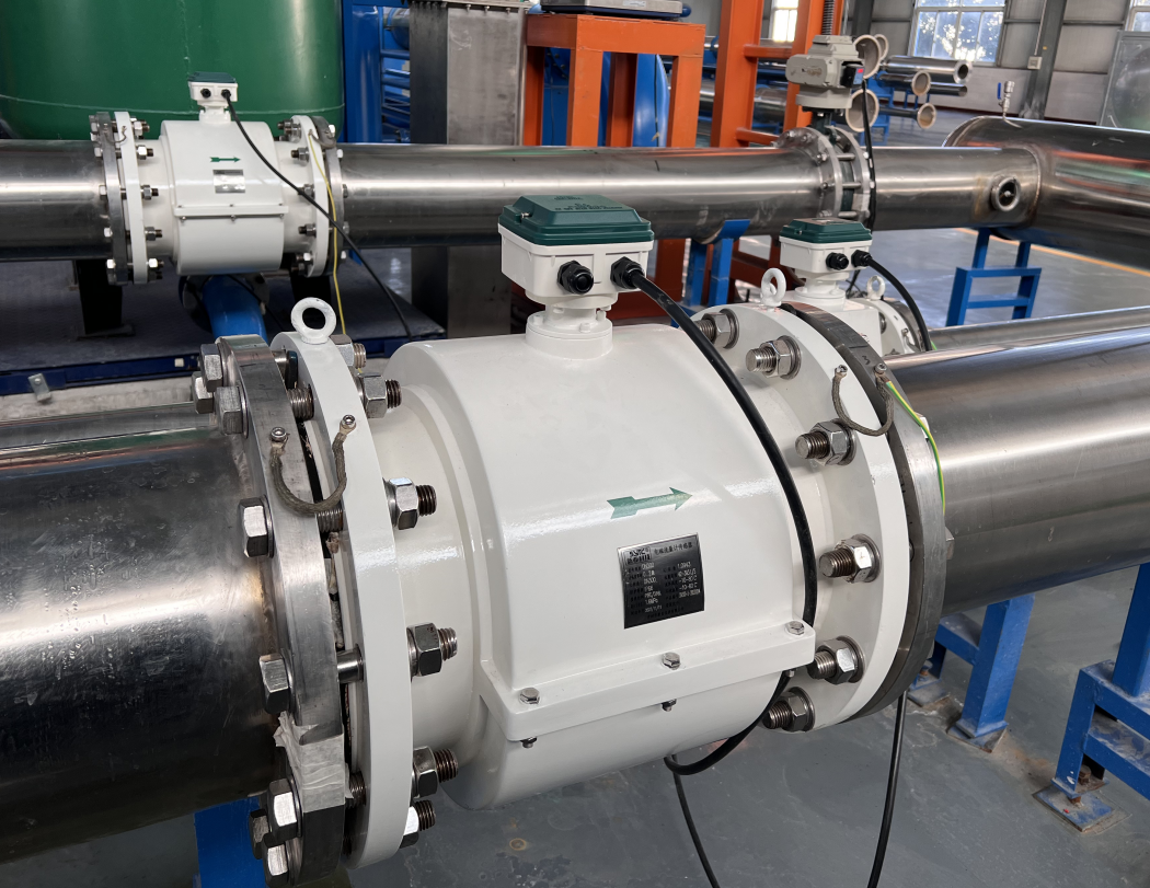
- Grounding: Proper grounding rings or grounding electrodes are required to establish a stable reference potential and avoid stray-current interference.
- Protection rating: Sensors installed in wet pits, below-grade vaults, or exposed mechanical rooms should have an appropriate IP rating (for example, IP68-rated sensors are suited to submerged or frequently wet locations, while IP65/66/67-rated converters suit standard indoor mechanical spaces).
- Calibration: Establish a calibration interval and verification method appropriate to the criticality of the measurement point.
H1: How Flow Measurement Supports Cooling Control and Energy Management
Reliable flow data is a foundational input for several data center cooling functions:
- Cooling control: Variable-speed pump control, valve modulation, and sequencing logic often use flow feedback to maintain design flow rates across CRAH units or cooling loops.
- Hydraulic balancing: Flow measurements at multiple loop segments help confirm that distribution matches design intent, especially after commissioning changes or capacity expansions.
- Monitoring and trending: Continuous flow data feeds building automation systems (BAS) for historical trending, alarm thresholds, and operational visibility.
- Energy management: Flow rate is one of two required inputs — along with supply and return temperature — for calculating cooling capacity or thermal energy consumption (commonly expressed using enthalpy-based or delta-T based calculations).
H2: Flow Measurement Is Not the Same as Energy Measurement
It is important to distinguish flow measurement from cooling capacity and energy measurement:
- A flow meter reports volumetric flow rate (e.g., liters per second, m³/h, GPM).
- Thermal energy or cooling capacity (kW, tons, BTU/hr) requires flow rate combined with accurately paired supply and return temperature measurements, using an enthalpy difference (Δh) or delta-T calculation.
- Errors in temperature sensor placement, response time, or calibration will distort energy calculations even if the flow measurement itself is accurate.
Facility teams designing energy submetering or cooling-capacity dashboards should treat the flow meter and temperature sensors as a paired measurement system, not independent devices.
H1: Common Problems in Data Center Cooling Flow Measurement
H2: Air Entrainment and Partially Filled Pipes
Air pockets or partially filled horizontal runs distort the electromagnetic signal and produce unstable or inaccurate readings. Vertical installation with upward flow, or installation downstream of air-elimination devices, can reduce this risk.
H2: Low Conductivity from Water Treatment
Some water treatment chemistries or high-purity makeup water can reduce conductivity below the meter’s minimum threshold. This should be checked during system water chemistry review, not only at initial commissioning.
H2: Pump-Induced Turbulence
Installing a flow meter too close to pump discharge, control valves, or elbows can introduce turbulent flow profiles that affect signal stability. Manufacturer-recommended straight-pipe distances upstream and downstream should be followed.
H2: Poor Grounding
Inadequate grounding, especially in plastic-lined or coated pipe sections, can introduce electrical noise into the measurement signal. Grounding electrodes or grounding rings are commonly used to address this.
H2: Incorrect Sizing
A meter sized larger than the actual process flow range can operate at the low end of its velocity range, reducing signal-to-noise performance. Undersized meters may create excessive pressure drop or velocity-related wear.
H2: Flow Fluctuations
Rapid valve actuation, pump staging events, or VFD ramp rates can create transient flow fluctuations. Where relevant, damping or averaging settings in the converter can help stabilize displayed and transmitted values.
H2: Unsuitable Piping Configurations
Installing sensors immediately after tees, reducers, or partially open valves without adequate straight-run distance is a frequent root cause of measurement drift and should be avoided during design.
H1: Why No Moving Parts Benefits Continuous Cooling-Water Monitoring
Electromagnetic flow meters have no mechanical components (such as turbines or paddlewheels) directly in the flow path. This characteristic is relevant to data center cooling monitoring because:
- There are no rotating parts subject to mechanical wear from continuous flow.
- The unobstructed bore does not accumulate debris on moving components, which is useful in systems where water treatment residue or biological growth may be present over time.
- Continuous, uninterrupted signal generation supports real-time monitoring without periodic mechanical recalibration associated with wear-based sensing elements.
These characteristics support suitability for continuous monitoring applications; they do not eliminate the need for periodic calibration verification or maintenance inspection.
H1: Practical Selection Guidance for Data Center Cooling Applications
When specifying electromagnetic flow meters for chilled-water or condenser-water loops in data centers, engineers should:
- Confirm water/glycol conductivity against the meter’s minimum requirement.
- Match pipe diameter and expected flow range to the sensor’s rated velocity window.
- Select liner and electrode materials compatible with system temperature and water chemistry.
- Specify appropriate protection ratings for the installation environment (mechanical room vs. below-grade or wet locations).
- Plan installation location with adequate straight-pipe runs and proper grounding.
- Define an output signal type (4-20mA, pulse, frequency, or digital communication) that matches the BAS or IoT platform integration requirements.
- Establish a calibration and verification schedule appropriate for the criticality of the measurement point.
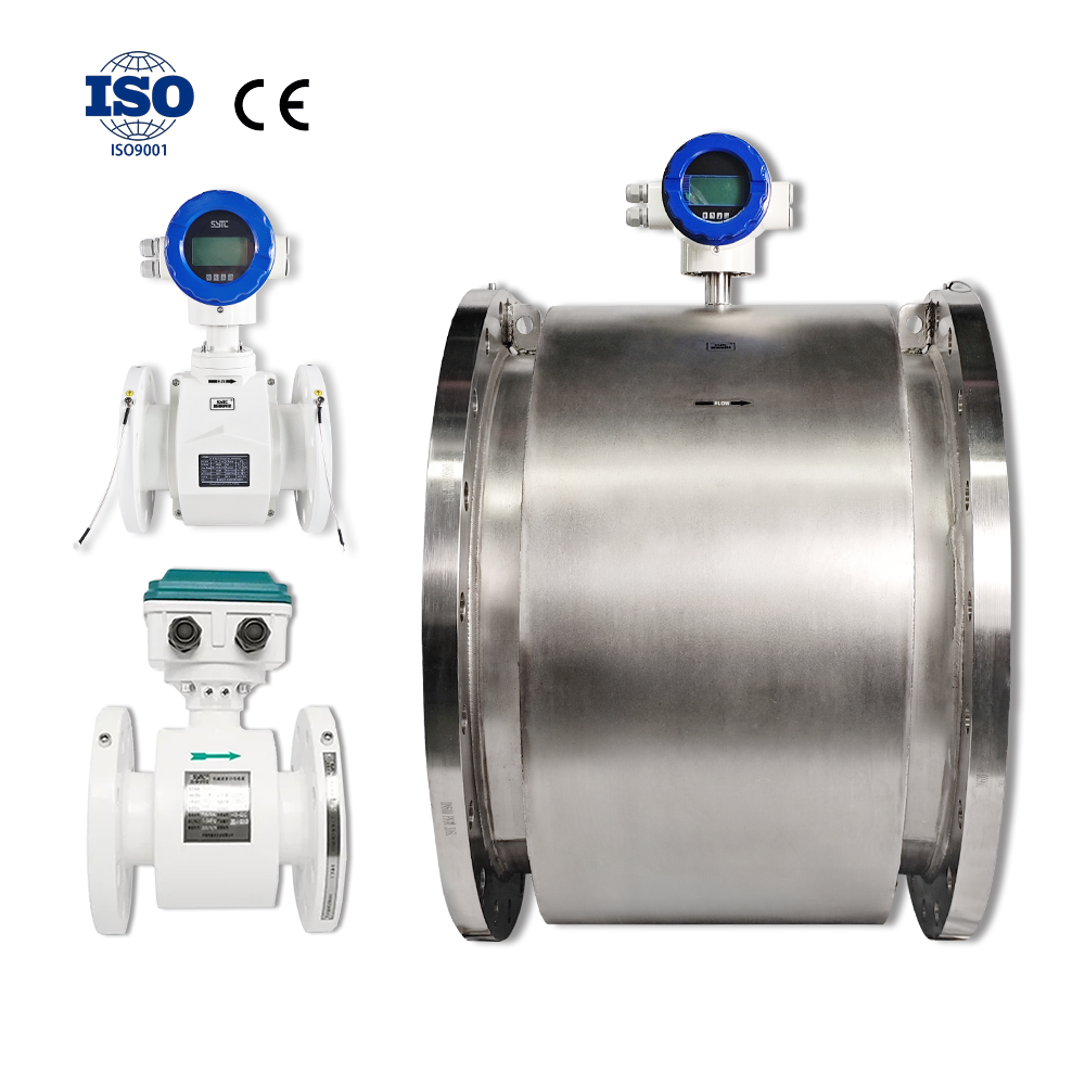
Suppliers such as Kaifeng Xinya Instrument Co., Ltd. produce electromagnetic flowmeter product lines — including standard industrial, battery-powered/wireless, insertion-type, and food-grade sanitary variants — that illustrate the range of configurations available for different pipe sizes, installation constraints, and communication requirements relevant to cooling-water applications. Facility engineers should evaluate specific model documentation against the project’s conductivity, pressure, temperature, and integration requirements.
H1: Frequently Asked Questions
Q1: Can electromagnetic flow meters measure glycol-water mixtures used in data center cooling loops?
A: Electromagnetic flow meters can measure glycol-water mixtures as long as the mixture retains sufficient electrical conductivity to meet the meter’s minimum requirement. Conductivity should be verified for the specific glycol concentration used.
Q2: Do electromagnetic flow meters measure cooling capacity directly?
A: No. Electromagnetic flow meters measure volumetric flow rate only. Cooling capacity or thermal energy requires combining flow rate with supply and return temperature measurements using an enthalpy or delta-T calculation.
Q3: What happens if a pipe is not completely full when using an electromagnetic flow meter?
A: Partially filled pipes can cause inaccurate or unstable readings because the meter relies on a full-pipe conductive path across the electrodes. Installation should ensure full-pipe conditions, often achieved through vertical upward-flow orientation.
Q4: How close can an electromagnetic flow meter be installed to a pump or valve?
A: Manufacturer-specified upstream and downstream straight-pipe distances should be followed to avoid turbulence-related signal disturbance. These distances vary by model and should be confirmed in product documentation.
Q5: Is grounding required for electromagnetic flow meters in cooling-water piping?
A: Yes. Proper grounding, typically via grounding electrodes or grounding rings, is required to maintain a stable reference potential and reduce electrical noise, particularly in non-metallic or lined piping sections.
Q6: What protection rating is needed for sensors in below-grade or wet mechanical spaces?
A: Sensors installed in submerged or frequently wet locations typically require higher ingress protection ratings (such as IP68), while converters in standard indoor mechanical rooms are generally suited to IP65/66/67 ratings. Actual requirements depend on installation conditions.
Q7: How often should an electromagnetic flow meter be calibrated in a data center cooling application?
A: Calibration intervals depend on the criticality of the measurement point, water chemistry, and facility maintenance policy. There is no universal interval; engineers should establish a verification schedule based on the specific application and manufacturer guidance.
H1: Summary
Electromagnetic flow meters are well suited to data center cooling-water applications because the working fluid is typically conductive, the measurement path is unobstructed, and the technology supports the wide flow ranges and bidirectional conditions found in chilled-water supply, return, primary/secondary loops, and heat exchanger circuits. Correct selection depends on evaluating conductivity, flow range, pipe diameter, temperature, pressure, full-pipe conditions, installation location, grounding, and protection rating. Flow measurement should always be understood as one component of cooling control and energy management — thermal-energy calculations require accurate temperature measurement alongside flow. Ongoing calibration and attention to common installation issues such as air entrainment, poor grounding, and turbulence help maintain measurement reliability across the cooling infrastructure lifecycle.
https://www.sytcflowmeter.com/
Kaifeng Xinya Instrument Co., Ltd.