When specifying an electromagnetic flow meter for an industrial or municipal project, the output and communication configuration is often decided too late — after the control panel is designed, the PLC I/O count is fixed, or the SCADA integrator has already committed to a specific protocol. This causes rework, added wiring, or costly signal converters after delivery. This article is written for system integrators, automation engineers, EPC contractors, distributors, and industrial buyers who need to specify the correct output configuration before placing a purchase order.
Why Output Specification Is a System Compatibility Decision, Not a Feature Checklist
Selecting outputs is not about choosing "the best" signal type. It is about matching the transmitter’s electrical interface to the existing or planned control architecture. The same flow meter model can be ordered with different output combinations, and the wrong choice can mean the device physically works but cannot be integrated without additional hardware.
4–20 mA analog output remains the default interface for buyers connecting to legacy PLCs, single-loop controllers, or panel indicators that only accept analog input cards. It is the safest default when the receiving equipment is unknown or mixed-vendor, because almost every analog input module supports it. However, it typically represents only the instantaneous flow rate — not totalized volume — so it should not be the only output specified if totalization or batch control is required downstream.
Pulse output is the practical choice when the receiving system (a local counter, batch controller, or PLC counter input) needs to accumulate volume directly through pulse counting rather than through software-based integration of an analog signal. Buyers should confirm the required pulse weight (volume per pulse) and pulse width compatibility with the receiving counter, since mismatched pulse weight leads to totalization errors that are not always caught during commissioning.
Frequency output and alarm outputs, where available on the transmitter, serve two different practical purposes. Frequency output is generally used where the receiving system prefers a scaled frequency signal instead of a raw pulse train, common in some flow computers. Alarm (relay/switch) outputs are typically used for discrete events — empty pipe detection, high/low flow threshold breach, or fault status — and are wired directly into a PLC digital input or an annunciator panel rather than into a data acquisition loop. These should be specified only if the control architecture actually has spare digital inputs allocated for them.
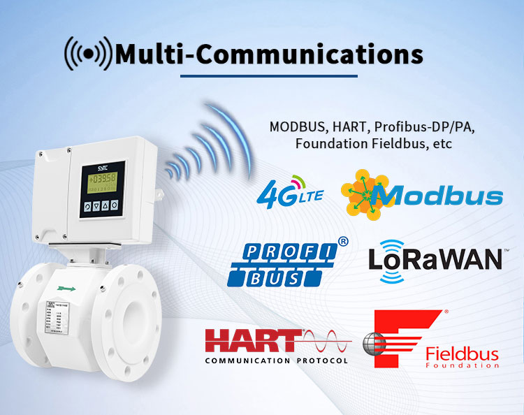
RS485 and Modbus RTU, where supported by the specific transmitter model, are used when the project requires digital data exchange rather than simple analog/pulse wiring — for example, reading multiple process values (flow rate, totalizer, diagnostics) over a single multidrop cable to a SCADA system or a remote terminal unit. RS485 is the physical layer; Modbus RTU is the protocol running on top of it. Buyers should not assume that RS485 hardware automatically means full Modbus register-level compatibility with their specific SCADA software — register maps, baud rate, and addressing must be confirmed against the transmitter’s technical documentation.
Digital communication requirements beyond Modbus — such as HART, GPRS, or wireless connectivity for IoT-based remote monitoring — should only be specified if there is an actual downstream system designed to consume that data. Adding digital communication "just in case" increases both cost and the risk of an unused, misconfigured interface sitting idle at commissioning.
How to Determine the Required Configuration
Rather than starting from the list of available outputs, buyers should start from the actual system requirements:
- PLC connection — Identify whether the PLC has analog input cards, digital counter inputs, or a communication port (RS485/Ethernet gateway) available, and how many spare channels exist.
- SCADA or monitoring system — Determine whether the SCADA platform polls devices via Modbus RTU, requires an OPC/gateway conversion, or expects cloud-based data delivery via an IoT platform.
- Flow totalization — Decide whether totalization will be calculated in the PLC/SCADA software from an analog signal, or whether the meter itself must provide a dedicated pulse/totalizer output.
- Remote data collection — For unmanned or off-grid sites, clarify whether data needs to be transmitted via GPRS/wireless to a central platform, which changes both the communication and power requirements of the transmitter.
- Alarm functions — List which fault conditions (empty pipe, overrange, excitation fault) must trigger a physical alarm output versus which can simply be read as a status bit over a digital protocol.
- Existing control architecture — Document what is already installed (cable type, existing gateways, protocol standards used in the plant) so the new meter is specified to fit into the existing system rather than requiring it to be modified.
Confirm Availability With the Manufacturer Before Ordering
It is important to note that not every output or communication option is available on every transmitter model or configuration. Analog, pulse, alarm, and RS485/Modbus availability generally depend on the specific transmitter series and the ordered configuration code, and combinations vary between manufacturers and even between product lines from the same manufacturer. Buyers should never assume a communication feature is included by default — it should always be confirmed directly with the manufacturer at the quotation stage, based on the exact model and configuration being purchased.
Information Buyers Should Provide to Avoid Interface Mismatch
To avoid receiving a meter with the wrong output configuration after delivery, buyers should provide the following at the time of inquiry:
- The type of receiving equipment (PLC brand/model, SCADA platform, flow computer, or local display)
- Required signal type(s): analog, pulse, frequency, alarm, and/or digital communication
- If digital communication is required: protocol (e.g., Modbus RTU), physical layer (RS485), baud rate, and whether a specific register map format is expected
- Power availability at the installation site (grid power vs. battery/solar, which affects whether GPRS/wireless communication is practical)
- Number and type of alarm conditions that must be wired to discrete outputs
- Whether totalization will be handled by the meter’s internal pulse output or by host-system calculation from an analog signal
Communication Specification Checklist
- [ ] Receiving system type identified (PLC / SCADA / flow computer / local panel)
- [ ] Spare I/O channels or communication ports confirmed
- [ ] Analog (4–20 mA) requirement confirmed or excluded
- [ ] Pulse output requirement and pulse weight defined
- [ ] Frequency/alarm output requirement defined, with digital input availability confirmed
- [ ] RS485/Modbus RTU requirement confirmed, including baud rate and register expectations
- [ ] Remote/IoT connectivity requirement (GPRS/wireless) confirmed against site power availability
- [ ] Manufacturer has confirmed availability of the required outputs on the specific model/configuration
- [ ] Cable and gateway requirements documented for installation team
FAQ
Q: Can one transmitter provide 4–20 mA, pulse, and Modbus RTU simultaneously?
A: Some transmitter models support multiple output types concurrently, but this depends on the specific hardware configuration ordered. It must be confirmed with the manufacturer rather than assumed from a general product brochure.
Q: Is RS485 the same as Modbus RTU?
A: No. RS485 is the physical wiring standard; Modbus RTU is a communication protocol that can run over RS485. A transmitter with an RS485 port does not automatically guarantee a specific register map matching your SCADA configuration — this should be verified against the device’s communication manual.
Q: Do we need pulse output if we already have 4–20 mA?
A: Only if totalization needs to be performed by counting pulses rather than by software integration of the analog signal in your PLC or SCADA. Many systems calculate totals from the analog value, making a separate pulse output unnecessary.
Q: What happens if we don’t specify communication requirements clearly?
A: The most common outcome is receiving a device with default analog output only, which then requires an additional signal converter, gateway, or even a transmitter exchange to match the actual control system — adding cost and delay to project commissioning.
Closing Note
Getting the output and communication specification right at the purchase order stage prevents rework during commissioning and ensures the flow meter integrates cleanly into the intended control architecture. Kaifeng Xinya Instrument Co., Ltd., a manufacturer of electromagnetic flow measurement systems, configures its SF-E, SF-C, SF-W, and battery-powered/wireless flow meter series with 4–20 mA, pulse, frequency, alarm, and RS485-based communication options according to each project’s electrical and communication requirements. As with any manufacturer, the exact combination of outputs and protocols available depends on the specific model and configuration ordered, so buyers should confirm the final specification directly with the technical team before finalizing a purchase order — rather than assuming universal compatibility with every PLC, SCADA, or industrial control system on the market.
https://www.sytcflowmeter.com/
Kaifeng Xinya Instrument Co., Ltd.