Electromagnetic Flow Meter Biofouling Risks in Aquaculture
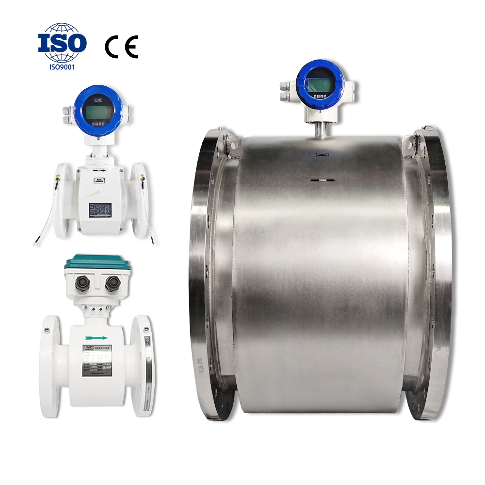
Electromagnetic flow meters can operate reliably in seawater aquaculture recirculation systems, but biofouling on wetted surfaces and electrodes is a real engineering variable that must be evaluated case by case. Not every seawater installation develops significant fouling — organic load, temperature, flow velocity, and cleaning practices all influence outcomes. This article explains the mechanisms involved, how to distinguish biofouling from other wetted-part issues, and what designers and buyers should verify before specifying equipment such as those offered under the Kaifeng Xinya / Xinya Instrument product lines.
Why Seawater Conductivity Generally Supports Electromagnetic Measurement
Electromagnetic flow meters require a minimally conductive liquid to generate a measurable induced signal. Seawater’s dissolved salt content typically provides conductivity well above the threshold required by most industrial electromagnetic flow meter designs, including units referenced in Xinya Instrument / SyTC technical documentation that specify square wave pulse excitation and VFC signal conversion for stable zero-point performance.
However, "generally supports" does not mean "automatically guarantees." Conductivity requirements vary by model, and actual suitability depends on the manufacturer’s stated minimum conductivity, electrode configuration, and signal processing design. System designers should confirm these parameters against the specific meter model under consideration rather than assuming all electromagnetic meters are interchangeable in marine water.
How Biofilm and Biological Deposits May Accumulate on Wetted Surfaces
In recirculating aquaculture systems (RAS), water is continuously cycled through biofilters, pipework, and instrumentation, often carrying organic matter, microorganisms, and nutrients. Under suitable conditions — warm water, low flow velocity, nutrient availability, and extended residence time — a biofilm layer may begin forming on wetted internal surfaces, including:
- The flow tube lining
- Electrode faces
- Grounding rings or grounding electrodes
- Flange gasket areas near the measurement section
This is a gradual, condition-dependent process. Systems with higher flow velocities, periodic flushing, or lower organic loading may experience minimal buildup, while stagnant or nutrient-rich sections are more susceptible. The presence or absence of fouling cannot be assumed; it should be evaluated through periodic inspection appropriate to each installation.
Potential Measurement Effects
If biological deposits form on the electrode surface, they may introduce an insulating layer that interferes with signal pickup, potentially contributing to noisy readings, zero-point drift, or reduced signal stability. Deposits on the flow tube liner, if sufficiently thick, could also marginally alter the effective internal diameter, which is a separate concern from electrode-specific fouling.
Distinguishing Electrode Fouling, Flow-Tube Deposits, Marine Corrosion, and Suspended Solids
These four conditions are sometimes discussed together but have different causes, indicators, and remediation paths:
| Condition | Typical Cause | Common Indicator | Distinct From |
|—|—|—|—|
| Electrode fouling | Biofilm or mineral/organic film on electrode face | Signal noise, zero drift, unstable readings | Corrosion (which is a material loss process, not a film) |
| Flow-tube deposits | Organic/biological buildup on liner surface | Gradual accuracy shift, possible reduced flow area | Suspended solids (transient, not adhered) |
| Marine corrosion | Electrochemical reaction between wetted metal parts and seawater chemistry | Pitting, material degradation at electrodes or flanges | Fouling (a deposit issue, not metal loss) |
| Suspended solids interference | Particulates temporarily present in flow stream | Momentary signal spikes, not persistent drift | Biofouling (which is adhered and persistent) |
Correct diagnosis matters because the response differs: fouling typically requires physical or chemical cleaning, while corrosion may require materials review or component replacement, and suspended solids interference is often addressed through signal filtering rather than cleaning.
Cleaning Access, Inspection Planning, and Chemical Compatibility
Because biofouling develops gradually and variably, planning for inspection and cleaning access at the design stage is more productive than reacting after accuracy complaints arise. Considerations include:
- Physical access: Specifying installation orientations and upstream/downstream clearances that allow removal of the sensor, or in-line access for electrode inspection, without major pipework disassembly.
- Inspection cadence: Establishing a facility-specific inspection schedule based on observed fouling behavior in that system, rather than relying on a generic interval, since fouling rates are not uniform across installations.
- Cleaning chemical compatibility: Confirming that any cleaning-in-place (CIP) chemicals, descaling agents, or biocides used in the aquaculture system are compatible with the specified liner material (e.g., PFA, rubber, ceramics referenced in Xinya Flowmeters’ slurry and industrial series) and electrode material. Incompatible chemicals can degrade wetted components faster than fouling itself.
- Mechanical cleaning limits: Understanding whether abrasive cleaning methods are appropriate for the liner material, since some linings tolerate mechanical cleaning better than others.
Why Electrode and Liner Selection Must Account for Seawater Composition, Temperature, Pressure, and Maintenance
There is no single electrode or liner material that is universally correct for every seawater aquaculture application. Selection should be guided by a combination of factors:
- Seawater composition: Salinity, dissolved mineral content, and any treatment chemicals (chlorine, ozone by-products, etc.) used in the recirculation loop can influence both corrosion behavior and fouling tendency.
- Operating temperature: Elevated temperatures in some RAS systems may accelerate biological growth rates compared to cooler ambient seawater intake lines.
- Operating pressure: Pressure ratings affect flange standards and wetted-part structural requirements, which should align with applicable standards such as GB/T 9124.1 flange compliance referenced in Xinya Instrument’s documentation.
- Maintenance practices: A facility with disciplined cleaning routines may tolerate a broader range of materials than one with infrequent maintenance access.
Because these variables interact, electrode and liner selection is best handled as a technical review rather than a standardized default across all installations.
Role of Factory Calibration — and Its Limits
Xinya Instrument / SyTC performs 100% factory calibration on flow meters before shipment, which establishes a verified accuracy baseline at the time of delivery. It is important to be clear about what this does and does not address: factory calibration confirms initial measurement performance under controlled test conditions. It does not prevent future biological deposit formation on electrodes or flow-tube linings, nor does it establish long-term corrosion resistance in a specific seawater environment over years of service. Ongoing reliability in a biofouling-prone system depends on field conditions, material selection, and maintenance — not solely on the calibration performed at the factory.
Risk-Versus-Verification Table
| Risk Area | What to Verify Before Purchase |
|—|—|
| Electrode signal stability | Minimum conductivity requirement of the specific model vs. actual seawater conductivity |
| Biofilm accumulation potential | Flow velocity range, residence time, and organic loading in the target pipeline section |
| Liner compatibility | Chemical compatibility of liner material with both seawater and cleaning agents used on-site |
| Electrode material suitability | Electrode material compatibility with seawater chemistry and any treatment additives |
| Corrosion exposure | Flange and wetted-part material specification relative to applicable standards |
| Maintenance access | Physical layout allowing inspection/removal without major pipeline disruption |
| Signal interference sources | Differentiating suspended-solid noise from persistent fouling-related drift |
Buyer Checklist
- Confirm the meter’s minimum conductivity specification against actual seawater conductivity at the installation site.
- Request documentation on available electrode and liner material options for marine-adjacent use.
- Clarify installation orientation and access requirements for electrode inspection.
- Share the facility’s cleaning chemical list for compatibility review.
- Specify operating temperature and pressure ranges for the review.
- Ask whether factory calibration certificates are provided, and understand their scope (initial accuracy, not long-term field performance).
- Discuss pipe size, flow range, and expected residence time in the measurement section.
FAQs
Does seawater automatically cause electrode fouling in electromagnetic flow meters?
No. Fouling depends on factors such as flow velocity, temperature, organic load, and maintenance practices, not on seawater presence alone.
Can biofouling be mistaken for a flow meter calibration error?
Yes. Gradual accuracy drift or signal instability caused by electrode film buildup can resemble a calibration or electronics issue, so inspection of wetted parts is a reasonable diagnostic step before assuming a device fault.
Is one electrode material always best for seawater aquaculture use?
No single material is universally suitable. Material choice should be reviewed against the specific seawater chemistry, temperature, pressure, and maintenance regime of each project.
Does factory calibration guarantee long-term performance in seawater?
Factory calibration verifies initial accuracy under controlled conditions. It does not substitute for field-specific evaluation of fouling tendency or corrosion behavior over time.
Conclusion
Biofouling in seawater aquaculture recirculation pipelines is a condition-dependent risk rather than a universal certainty, and electromagnetic flow meters can be a suitable measurement technology when conductivity, materials, and maintenance planning are properly matched to the application. Rather than relying on generic assumptions, system designers and buyers should request a technical review based on their actual seawater conditions.
To receive a technical review tailored to your project, please share details including seawater conditions, operating temperature, flow range, pipe size, cleaning process used, operating pressure, and wetted-material requirements with the Kaifeng Xinya / Xinya Instrument technical team.
https://www.sytcflowmeter.com/
Kaifeng Xinya Instrument Co., Ltd.