What engineers and buyers get wrong about the 1.0mm LVDS display connector — and how to cross-reference it without breaking a design.
A few years ago a customer sent us a drawing for a display harness. The connector on it was labelled “JST DF19.”
There is no such part. The DF19 is a Hirose Electric series, and there is no JST series designated DF19. The mistake was caught before tooling, but it is the kind of thing that gets caught late — after a footprint is committed, after a cable drawing is released, after someone has ordered from a part number that does not exist.
The DF19 is worth understanding properly, because it is genuinely unusual among wire-to-board connectors. It is the interface behind a very large share of small LCD panels, and it does something almost no other series does. It is also the series where the most-quoted specification — the current rating — is usually quoted wrong.
Here is the whole thing, with every figure traced to Hirose’s or KONNRA’s own published documentation, and the places where the two disagree flagged rather than averaged.
The one-minute version
The Hirose DF19 is a 1.0mm pitch, single-row, low-profile wire-to-board connector, supplied in 8, 14, 20 and 30 contacts. Hirose describes it as the de facto standard for LCD panel connections on panels under 12 inches, and as a high-performance connector for LVDS high-speed differential signals.
- Pitch: 1.0mm, single row
- Positions: 8, 14, 20, 30 — four counts, no others
- Voltage rating: 100V AC
- Current rating: 1A / 0.9A / 0.8A / 0.5A / 0.5A / 0.3A — depending on how you terminate it (this is the important part, below)
- Operating temperature: −35°C to +85°C, including temperature rise from current flow
- Contact resistance: 30mΩ max, or 50mΩ max on the FPC path
- Durability: 30 insertion/withdrawal cycles
- Receptacle heights: 1.65mm, 1.1mm or 1.0mm depending on mounting style
- Cross-reference equivalent: KONNRA KR1002, documented from 8 to 30 circuits
The defining feature is not any of those numbers. It is that one receptacle accepts three different kinds of cable.
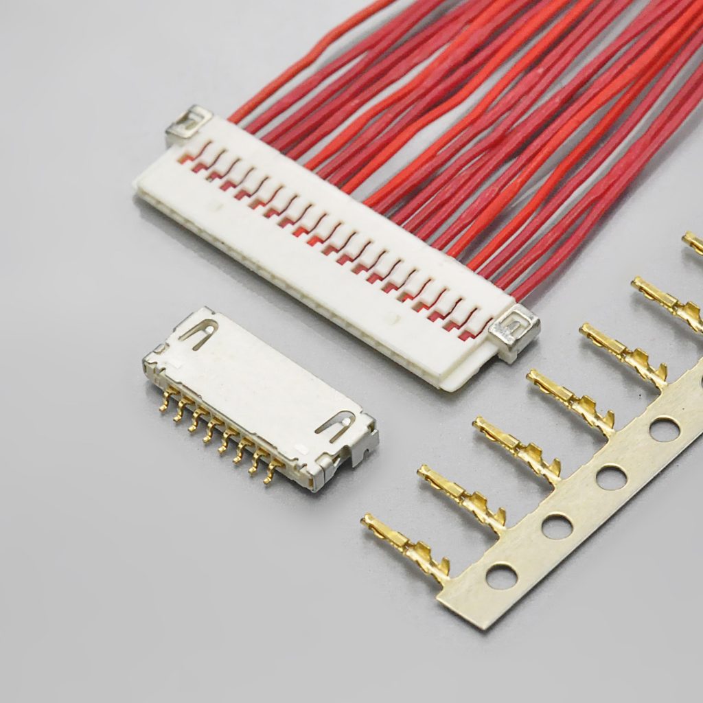
One receptacle, three cable systems
Most wire-to-board connectors accept exactly one kind of cable. The DF19 accepts three:
- Crimped discrete wire — ordinary insulated hook-up wire crimped into a contact and inserted into a plug housing. Plug part numbers look like
DF19-…S-1C, orDF19G-…S-1C(05)when a grounding plate is fitted. - FPC — a flat flexible circuit folded into the plug (
DF19G-…S-1F(05)). - Micro-coaxial cable — fine coax soldered to the contact (
DF19G-…S-1SD(05)).
Two Hirose design rules sit behind that list, and both are easy to miss:
The same receptacle serves all three. A board design can commit to one footprint and still leave the cable architecture open — which is exactly what you want when the same product ships in more than one cable configuration.
The plug’s external dimensions do not change. Whether the plug is terminated with discrete wire, FPC or micro-coaxial cable, its external dimensions stay the same. A mechanical envelope you validated for a crimped harness stays valid if the build later switches to an FPC tail.
There is a catch, though, and it matters enormously when you cross-reference the part: grounding plates are required for the FPC and micro-coaxial paths. They are not accessories. They are separate line items, ordered under their own part numbers (DF19G-14S-1F-GND(05), and so on), installed with their own tooling.
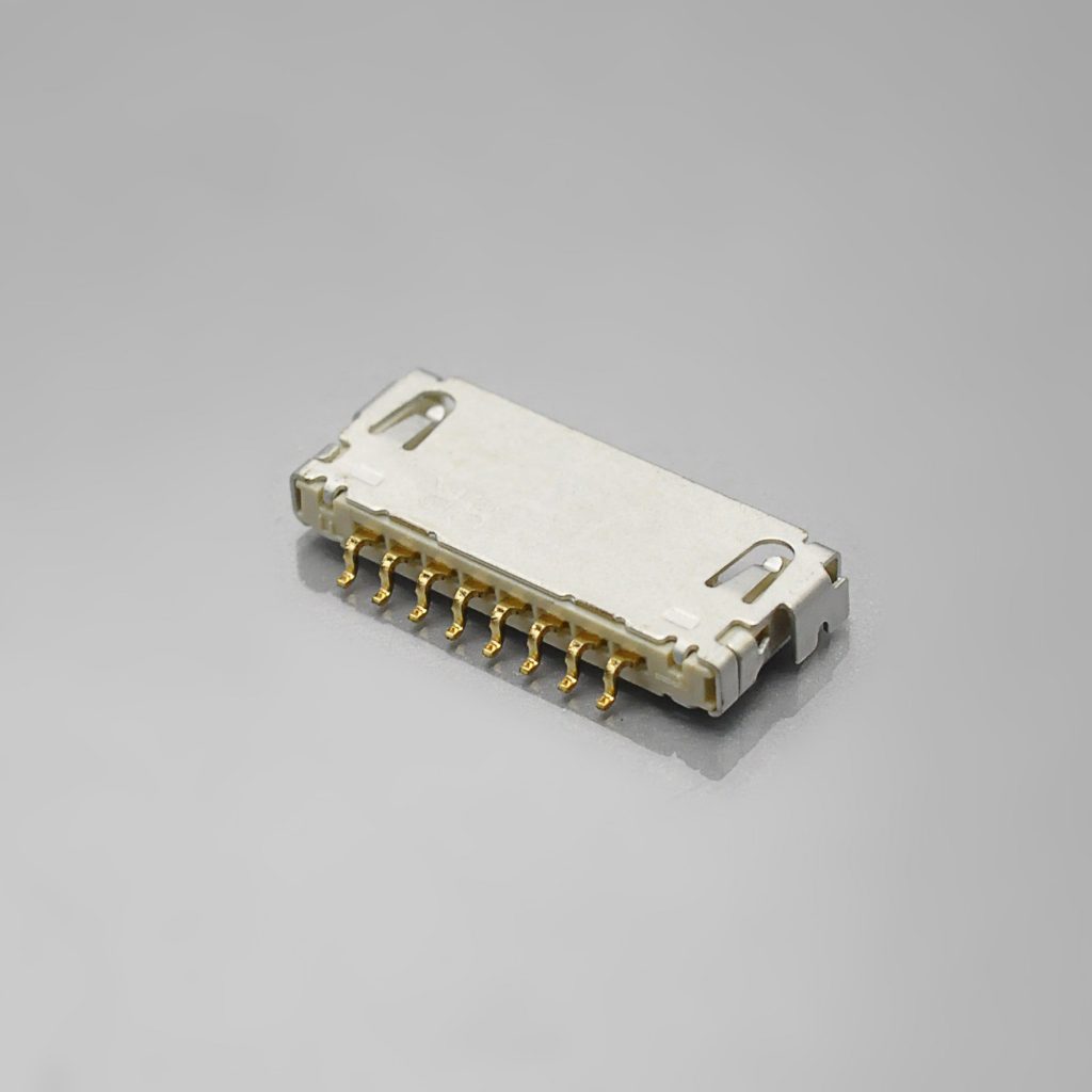
So a DF19 replacement is not one connector — it is an interface. If your design only uses the discrete-wire route, a crimp-style equivalent can cover it. If your design depends on the FPC or micro-coaxial route, the plug bodies and grounding plates are part of the requirement, and they are not interchangeable with a housing and a terminal.
The current rating is not 1A. It is six numbers.
If you take one thing from this article, take this one.
The DF19 does not have a single current rating. It has six, and the one that applies to you depends on your conductor and termination:
- AWG #28 (7/0.127mm) — 1.0A
- AWG #30 (7/0.1mm) — 0.9A
- AWG #32 (7/0.08mm) — 0.8A
- AWG #36 (7/0.05mm) — 0.5A
- FPC (t = 0.145±0.03mm) — 0.5A
- AWG #40 micro-coaxial cable — 0.3A
Why the number moves. A 1.0mm pitch contact has a fixed contact area. At AWG #28 the contact itself is the limiting element, and the rating is 1A. As the conductor gets finer, the wire becomes the bottleneck instead, and Hirose’s published rating falls with it — 0.9A at #30, 0.8A at #32, 0.5A at #36. Terminate with an FPC or micro-coax and the conductor cross-section drops again, to 0.5A and 0.3A.
Why this bites. A catalogue, a marketplace listing or a cross-reference table that describes the DF19 as “1A” is quoting the AWG #28 figure. That number is correct — for AWG #28. If your harness is built with AWG #32, the applicable rating is 0.8A, and a design that assumed 1A has no margin at all. If you are driving a panel supply rail through an FPC tail, the applicable figure is 0.5A.
There is a second-order consequence that is easy to overlook: fault current and temperature rise are part of the temperature specification. Hirose states its −35°C to +85°C range includes the temperature rise caused by current flow. Size a signal connector at a current it was never rated for and you erode that margin from the inside.
Pin counts: four, and the arithmetic that catches errors
Hirose catalogues the DF19 in exactly four contact counts: 8, 14, 20 and 30. There are no intermediate counts. A connector with 16 or 24 positions at 1.0mm pitch is not a DF19, whatever the label says.
The contact field width scales predictably, which gives you a free cross-check. For every through-board style, the receptacle “A” dimension is:
3.55mm + (number of contacts × 1.0mm)
- 8 contacts → 11.55mm
- 14 contacts → 17.55mm
- 20 contacts → 23.55mm
- 30 contacts → 33.55mm
If a drawing or a quotation quotes a different A dimension for a given contact count, one of the two numbers is wrong — and it is worth finding out which before you release anything.
Reading a DF19 part number
Every DF19 part number encodes the same set of fields. Taking DF19G-20P-1H(54) apart:
DF19— series- Configuration letter — see the trap below
20— number of contactsP— connector type:P= receptacle,S= plug1— 1mm pitchH— mounting or termination type:Hhorizontal SMT,Vvertical SMT,Cplug for discrete wire,Fplug for FPC,SDplug for micro-coaxial cable(54)— packaging: tape and reel, 1,000 pcs/reel.(05)is a bag of 100;(56)is the tape and reel used for the vertical receptacle.
The trap: G means two different things
On a receptacle, a leading G means top-board mounting:
DF19G-20P-1H(54)— a receptacle, top-board mounting, 20 contacts, 1.65mm high
On a plug, a leading G means the grounding plate is fitted:
DF19G-20S-1C(05)— a discrete-wire plug, 20 contacts, with grounding plate
Reading DF19G as a single concept across both receptacles and plugs is the most common part-number error on this series — and it is the kind of error that produces a harness that fits nothing.
The crimp contacts use their own numbering scheme, by the way: DF19A-2830SCFA covers 28–30 AWG, DF19A-3032SCFA covers 30–32 AWG, and DF19A-3336SCFA is the fine-wire contact for 36 AWG. The contacts overlap at 30 AWG, and which one is correct depends on the strand construction of your cable, not on the gauge alone.
Mounting styles: the choice is really about board height
Hirose offers four right-angle configurations and one vertical, and the selection is driven almost entirely by how much height you have above the PCB:
- Top-board mounting —
DF19G-…-1H(54)— 1.65mm — 8, 14, 20, 30 contacts - Offset mounting —
DF19K-…-1H(54)— 1.0mm — 20, 30 contacts - Offset mounting —
DF19L-…-1H(54)— 1.1mm — 14, 20, 30 contacts - Reverse offset mounting —
DF19KR-…-1H(54)— 1.0mm — 14, 20 contacts - Vertical —
DF19-…-1V(56)— 14, 20 contacts
Three things to watch:
The offset styles overhang the board edge. Hirose’s mounting patterns for these variants show the plug envelope extending beyond the receptacle outline. You need to check the board edge clearance and the volume in front of the connector — not just the footprint.
There is a keep-out under the receptacle. The recommended mounting pattern carries an explicit “no conductive traces” note under the connector outline. Plan your ground pour and differential-pair routing around it rather than discovering it at layout review.
The vertical style uses different packaging. A (56) suffix is tape and reel at a 400mm reel diameter, unlike the (54) reel the right-angle styles use.
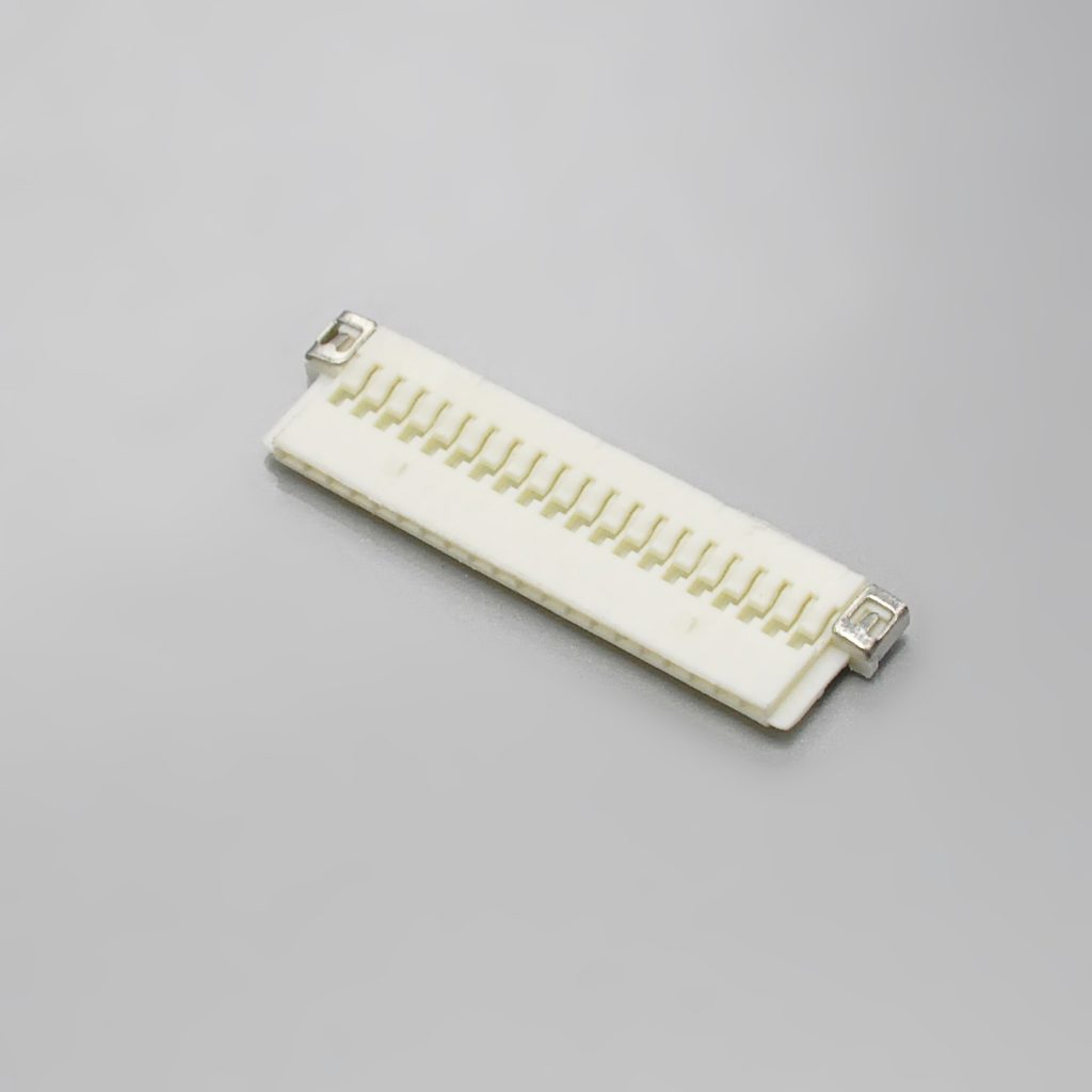
Cross-referencing it — including what the documentation does not cover
The KONNRA KR1002 series is documented as the cross-reference equivalent: 1.0mm pitch, single row, 8 to 30 circuits, 1A and 100V, supplied as a right-angle SMT wafer with a housing and a crimp terminal, plus pre-crimped cable assemblies and adapter harnesses.
If you are qualifying a second source, the headline match is the easy part. What matters is where the documentation stops. Here is the straight version.
The 3-in-1 interface is only partly covered. The wafer, the housing and the crimp terminal cover the discrete-wire route. No FPC plug, no micro-coax plug and no grounding plate is documented on the KONNRA side. If your design uses those paths, they need to be confirmed or sourced separately.
Durability is unpublished on the KONNRA side, while Hirose rates the DF19 at 30 insertion/withdrawal cycles. That is a low number for a connector in a product that may be serviced. Design so the display connector is not the one being repeatedly cycled, and if your service model depends on re-mating, ask for cycle data.
Plating is described differently. Hirose specifies gold-plated contacts for both the receptacle and the crimp contact. KONNRA documents gold flash / tin over nickel. Gold flash is a thin gold deposit rather than a full gold plating, and the two are not equivalent in thickness or long-term contact stability. Neither document states a thickness in microns — so ask for the figure if contact finish matters to your qualification.
Position counts: four discrete counts versus a range. Hirose catalogues 8, 14, 20 and 30. KONNRA documents 8–30 circuits. Confirm which counts are actually tooled before a drawing depends on an intermediate count.
Withstanding voltage and operating temperature differ. Hirose specifies 300V AC for one minute with no flashover or insulation breakdown, and −35°C to +85°C. KONNRA documents 500V AC per minute and −40°C to +105°C. Note that the KONNRA withstanding figure is the higher one, which is the reverse of the usual pattern — confirm the test basis (between which points, for how long, on which variant). And if your application genuinely relies on operation above +85°C, request the test data rather than accepting the headline range.
Applicable wire is specified narrowly by Hirose and loosely by KONNRA. Hirose accepts jacket diameters of 0.5–0.6mm for 28–32 AWG and 0.27mm for 36 AWG, requires tin-plated stranded annealed copper, and recommends UL1571 thin-wall cable. Strip length is 1.2mm to 1.9mm — outside that window the crimp either loses conductor strands or bites into insulation. KONNRA documents insulation O.D. 0.8mm max, which is wider than any Hirose-compliant cable. Hirose-compliant cable therefore sits well inside the KONNRA window — but heavier insulation that would fail Hirose’s specification would still pass KONNRA’s, so pin the accepted dimensions to the drawing for your specific assembly.
Tooling. Hirose requires its own applicator (AP105-DF19S) and press (CM-105C) for this series, and states that use of tools other than approved Hirose Electric tools will void the product warranties. If you build harnesses in-house this constrains you to Hirose tooling, or to a supplier who has it. If you buy finished assemblies, the tooling question becomes the supplier’s — and it is worth asking directly, because a supplier who cannot name their applicator is telling you something.

The pre-release checklist
Run this before releasing a drawing for anything in the DF19 family.
- Series confirmed by part number, not by pitch. DF19, DF20, DF50 and FX15 are all 1.0mm; DF13 and DF14 are 1.25mm. None of them mate with any other.
- Brand confirmed. The DF19 is a Hirose series. There is no JST DF19. If your drawing says “JST DF19”, the drawing is wrong.
- Termination type decided — discrete wire, FPC or micro-coaxial — and the plug part number matches it:
C,ForSD. - Grounding plate specified if the design uses the FPC or micro-coax path. It is required, and it is a separate line item with its own tooling.
- Current rating checked against your actual wire, not the headline 1A. AWG #32 gives 0.8A; AWG #36 and FPC give 0.5A; AWG #40 micro-coax gives 0.3A.
- Mating cycle count accepted — rated durability is 30 cycles. If your service model needs more, that is a design change, not a sourcing change.
- Mounting style and board height confirmed — 1.65mm for top-board, 1.0mm or 1.1mm for the offset styles — and the plug envelope checked as well as the receptacle footprint.
- The “no conductive traces” keep-out under the receptacle respected in the copper pour.
- Jacket diameter inside the specification for the wire you intend to use.
- Strip length set to 1.2–1.9mm on the harness drawing.
- Crimp tooling identified, and the warranty implication understood.
The rule that saves the most time
At 1.0mm pitch, cross-reference on the part number — never on the pitch, and never on appearance. Hirose alone sells four series at 1.0mm, JST sells another, and none of them mate with each other. A DF19 receptacle will not accept a JST SH plug, and a JST SH header will not accept a DF19 plug. If one end of your design is a DF19 and the other end of the harness is a JST SH, you need a transition harness rather than a direct mate.
Everything above — the full part-number cross-reference, the crimp contact and applicable-wire tables, the tooling part numbers, and the complete list of specification differences to verify — is in the full write-up:
➡️ Hirose DF19 Connector Complete Guide
Disclosure: I work with KONNRA, which manufactures the KR1002 cross-reference to the DF19. The Hirose DF19 figures in this article are taken from Hirose Electric’s published DF19 series documentation and catalog; the KONNRA figures are from KONNRA’s published KR1002 documentation. Where the two disagree, I have flagged the difference rather than averaged it — and where a parameter is not stated in either document, I have said so instead of filling the gap.
https://konnra.com/hirose-df19-connector-complete-guide/
Dongguan Konnra Electronics Co., Ltd