A hobbing gear machine is a core piece of equipment for manufacturers producing cylindrical gears, helical gears, splines, sprockets, and other components that require consistent tooth geometry. In automotive transmissions, industrial reducers, motorcycles, pumps, and power transmission systems, gear quality directly affects noise, vibration, load distribution, transmission efficiency, and service life. Selecting the right machine therefore requires more than comparing maximum workpiece diameter or spindle speed. Cutting accuracy, machine rigidity, tool compatibility, production cycle time, and long-term operating stability must be evaluated together.
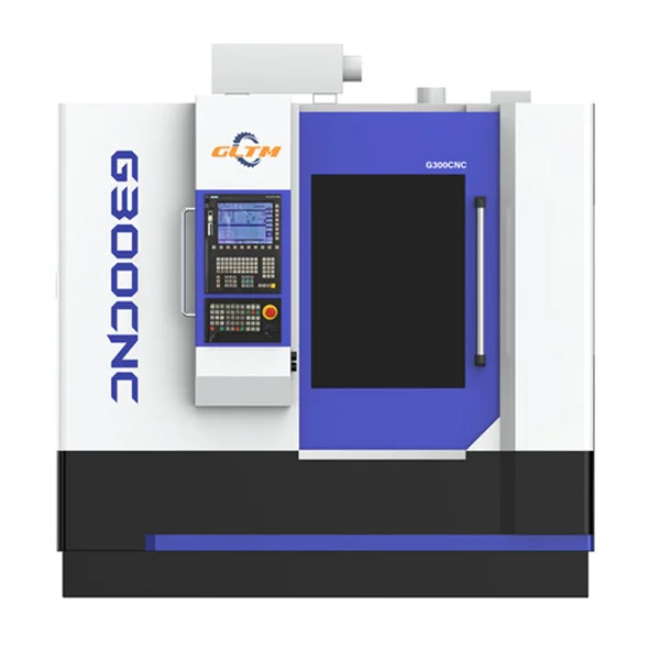
For manufacturers handling repeated production batches or a broad range of gear specifications, the main challenge is maintaining consistent tooth geometry while controlling machining costs. Excessive vibration can affect surface finish, thermal changes can influence dimensional stability, and unsuitable cutting parameters can accelerate hob wear. A well-configured hobbing gear machine helps address these challenges through synchronized cutting motion, rigid machine construction, precise positioning, and repeatable process control.
Wuxi General Machinery Co., Ltd. (GLTM / GLT) specializes in CNC gear hobbing machines and related gear manufacturing equipment. Since beginning production of high-speed, high-efficiency CNC gear hobbing machines in 2012, the company has developed a product range from the G80CNC series to large-capacity models such as the G2000CNC, alongside spline milling machines and other gear processing equipment. Its machine designs emphasize rigidity, efficiency, and reliability, providing a practical foundation for evaluating gear production requirements across different industrial applications.
How a Hobbing Gear Machine Generates Gear Teeth
Gear hobbing is a continuous generating process in which a rotating hob and a rotating workpiece move in a synchronized relationship. The hob resembles a worm with cutting edges arranged along its flutes. As the hob rotates, the workpiece rotates at a coordinated ratio, allowing the cutting edges to progressively generate the required tooth spaces.
For a conventional single-start hob, the relationship between hob rotation and workpiece rotation is determined by the number of teeth being produced. If the workpiece has \(Z\) teeth and the hob has one start, one complete hob revolution corresponds to a workpiece rotation of \(1/Z\) revolution, subject to the required direction and machine synchronization. Multi-start hobs change this ratio according to the number of starts.
The generating principle makes a hobbing gear machine particularly suitable for repeatable production of external cylindrical gears. With an appropriate machine configuration and tooling, the process can also support helical gears, splines, sprockets, synchronous belt pulleys, and selected specialized tooth profiles.
Unlike form milling, which uses a cutter profile corresponding to a particular tooth space, hobbing generates the tooth geometry through coordinated motion. This makes it suitable for high-volume production and for manufacturing different gear specifications using compatible tooling and machine settings.
However, not every gear can be produced directly by hobbing. Internal gears, certain complex geometries, and applications with restricted tool access may require gear shaping, power skiving, or another specialized process. The machine selection should therefore begin with the actual component drawing, gear geometry, material, and production volume rather than a general assumption that one process can cover every gear type.
Machine Rigidity and Its Influence on Gear Accuracy
Machine rigidity is fundamental to maintaining consistent tooth geometry under cutting loads. During hobbing, the hob, workpiece, fixtures, spindle systems, and machine structure form a connected mechanical system. If any part of this system deflects excessively, the cutting conditions may become unstable, leading to profile deviations, surface irregularities, or inconsistent results between parts.
A hobbing gear machine must resist cutting forces while maintaining the relative positions of the hob and workpiece. Structural deformation can become more significant when machining larger gears, cutting harder materials, using aggressive feed rates, or extending tool overhang. These conditions increase the importance of machine-bed stiffness, column stability, spindle support, and fixture design.
GLTM's CNC gear hobbing machine series uses a double-wall structure with high-ribbed plates for its main castings, with finite element analysis applied during structural design. This approach is intended to balance overall rigidity and machine stability. The actual machining results, however, depend on the complete configuration, including spindle condition, workholding, tooling, cutting parameters, and maintenance.
Accuracy should be evaluated using measurable gear characteristics rather than machine construction claims alone. Depending on the application, inspection may include tooth profile deviation, helix deviation, pitch deviation, runout, and dimensional consistency. Applicable gear accuracy standards and acceptance limits should be specified in the part drawing or quality plan.
For precision reducers and transmission components, these measurements help determine whether the machine can maintain the required quality over repeated production cycles. For less demanding applications, the necessary accuracy level may differ, but repeatability remains important because inconsistent parts can complicate assembly and increase downstream inspection or rework.
Choosing the Right Machine Size and Configuration
The maximum workpiece diameter is an important starting point when selecting a hobbing gear machine, but it should not be the only criterion. Workpiece height, module, tooth count, helix angle, face width, fixture dimensions, tool clearance, and the required machining operations can all affect the usable capacity of the equipment.
A machine should be selected with sufficient capacity for the largest realistic production part while retaining the rigidity and control capabilities needed for smaller, precision components. Choosing a machine that is too small can restrict future production, while selecting an unnecessarily large model may increase capital cost and floor-space requirements.
GLTM offers a broad range of CNC gear hobbing machines, including the G80CNC, G100CNC, G160CNC, G200CNC, G250, G300CNC, G400CNC, G500CNC, G600CNC, G800CNC, G1000CNC, G1200CNC, G1500CNC, and G2000CNC. The appropriate model depends on its verified technical specifications and the intended gear application; the model designation alone should not be treated as a confirmed maximum cutting diameter.
|
Selection factor |
Technical information to verify |
Production impact |
|---|---|---|
|
Workpiece capacity |
Maximum diameter, height, weight, and fixture envelope |
Determines whether the actual part can be accommodated |
|
Gear geometry |
Module, tooth count, helix angle, face width, and profile requirements |
Establishes process feasibility |
|
Hob spindle |
Speed range, power, torque, and tooling interface |
Influences cutting capability and cycle time |
|
Workpiece spindle |
Speed, indexing capability, and synchronization accuracy |
Affects generating accuracy and process stability |
|
CNC functions |
Supported axes, interpolation, programming, and automation interfaces |
Determines setup flexibility and integration |
|
Machine structure |
Rigidity, vibration behavior, and thermal stability |
Influences repeatability and surface quality |
Before confirming a configuration, manufacturers should provide representative part drawings and clarify which gears must be completed on the machine. This enables the equipment supplier to assess tooling access, required axes, fixture design, and any special processing requirements.
Cutting Parameters, Tool Wear, and Cycle Time
A hobbing gear machine can only deliver consistent results when its cutting parameters are matched to the material, gear geometry, hob design, and required quality. Cutting speed, axial feed, radial infeed, hob geometry, number of starts, and cutting fluid conditions all affect productivity and tool life.
Increasing cutting speed may reduce machining time, but the benefit can be offset by faster tool wear, thermal effects, or deteriorating surface quality if the process is not properly matched to the cutting tool and workpiece material. Similarly, excessive feed may increase cutting forces and vibration, while conservative settings can extend the production cycle unnecessarily.
The best operating window is therefore determined through controlled trials. For example, a manufacturer producing steel gears for industrial reducers may need to balance tool life and cycle time across long production runs. A factory machining smaller sprockets in batches may place greater emphasis on quick setup, consistent indexing, and reduced non-cutting time.
Hob condition is another important variable. Worn cutting edges can increase cutting forces, degrade surface finish, and affect tooth geometry. A maintenance strategy should establish inspection criteria, tool-life tracking, resharpening or replacement intervals, and consistent tool-setting procedures.
Coolant delivery and chip evacuation should also be considered. Poor chip removal can allow chips to interfere with the cutting zone, while unsuitable lubrication or cooling conditions may contribute to tool wear and inconsistent machining. The appropriate arrangement depends on the material, cutting tool, machine enclosure, and production requirements.
When optimizing cycle time, it is useful to separate actual cutting time from loading, clamping, tool changes, measurement, and other non-cutting activities. CNC automation can reduce some of these losses, but the expected improvement should be assessed using the complete production cycle rather than the cutting pass alone.
CNC Automation and Production Flexibility
CNC gear hobbing machines provide programmable control of coordinated axes, supporting repeatable production and reducing reliance on manual adjustments for every workpiece. Once a process has been validated, stored programs and standardized setup procedures can help reproduce machining conditions across production batches.
This is particularly useful for manufacturers supplying several gear variants to automotive, motorcycle, pump, and reducer industries. Product changes may require different fixtures, hobs, cutting parameters, or workpiece settings, but a structured CNC workflow can make these transitions more predictable.
Automation should be evaluated in relation to actual production needs. Automatic loading and unloading may improve utilization in high-volume environments, while flexible workholding and straightforward program management may be more valuable for factories handling frequent product changes. The expected benefit depends on batch size, changeover frequency, operator availability, and integration with upstream and downstream processes.
A hobbing gear machine should also fit into the wider gear manufacturing route. Depending on the accuracy and surface finish required, the process may be followed by deburring, gear grinding, inspection, or other operations. GLTM's wider equipment portfolio includes gear grinding, gear shaping, gear skiving, gear measuring, and gear chamfering machines, enabling manufacturers to evaluate related processes within a broader gear production plan.
The objective is not necessarily to perform every operation on one machine. It is to establish a reliable process route in which each machine performs the operations best suited to its capabilities.
Total Cost of Ownership and Quality Verification
The initial purchase price does not fully represent the cost of operating a hobbing gear machine. Total ownership cost also includes tooling, consumables, maintenance labor, electricity, machine downtime, inspection, rejected parts, and the cost of supporting the equipment over its service life.
A useful comparison measures cost per conforming gear rather than cost per machining cycle alone. A faster process may not be more economical if it creates additional scrap or requires frequent tool replacement. Conversely, improved repeatability and reduced setup time can produce measurable savings even if the nominal cutting speed remains unchanged.
Before finalizing an equipment investment, request a technical review based on representative components. The evaluation should cover achievable gear accuracy, cycle time, tooling requirements, changeover procedures, machine capacity, and maintenance access. Where possible, sample machining and inspection reports provide stronger evidence than general performance claims.
GLTM reports ISO 9001 and CE certifications and holds technical patents. These credentials can form part of a supplier assessment, but they do not replace verification of the exact machine configuration, applicable conformity requirements, and the quality of sample gears produced under representative conditions.
Conclusion
Selecting a hobbing gear machine requires a balance of gear accuracy, machine rigidity, usable capacity, cutting efficiency, CNC flexibility, and long-term operating cost. The most suitable equipment is the one that can consistently manufacture the intended gear geometry within the required tolerances while supporting the expected production volume and process route.
GLTM's range of CNC gear hobbing machines and complementary gear processing equipment provides options for manufacturers working across automotive components, motorcycles, industrial reducers, pumps, sprockets, and other power transmission applications. By verifying machine specifications, conducting representative cutting trials, and measuring the cost per conforming gear, manufacturers can make a more informed decision and build a gear production process that supports reliable quality and sustainable productivity.
www.gltmachinery.com
Wuxi General Machinery Co., Ltd.