Pico-SPOX, CLIK-Mate and Micro-Lock Plus all sit at 1.50mm and none of them mate — and on the Pico-SPOX itself, the two documents agree about almost everything except retention, where they differ fivefold.
Most cross-reference questions on this connector go wrong at the first step, before any specification is compared.
“1.50mm” does not identify a connector. Molex alone runs at least three different 1.50mm wire-to-board systems — Pico-SPOX, CLIK-Mate and Micro-Lock Plus — and they are not intermateable. They differ in retention concept and in current class. Getting the pitch right is the first step, not the answer.
And one of the names people search for does not exist as a Molex family. “Micro SPOX” appears in distributor listings but not on Molex’s own wire-to-board connector listing, which carries Mini-SPOX (2.50mm) and Pico-SPOX (1.50mm) in the SPOX class. If a drawing or a BOM says “Micro SPOX”, confirm the pitch and the series number on the manufacturer’s own documentation before cross-referencing anything.
On the second-source side there is a matching trap. KONNRA runs three series at or near 1.50mm — KR1500 (Molex Pico-SPOX), KR1501 (JST ZH 1.5mm) and KR1507 (Molex CLIK-Mate) — and they are three different products from two different original manufacturers. A quotation that offers “a 1.50mm equivalent” without naming which of the three it is has not answered the question.
Once the series is settled, the good news is that the two documents agree on more than they usually do: pitch, circuit range, voltage rating, withstanding voltage, contact resistance, insulation resistance, temperature rise, contact geometry, lock concept, crimp terminal retention force and the UL94 V-0 body rating all match. The problem is concentrated in two places — retention, where they differ by roughly fivefold, and the current ladder, which only one side publishes. Both are covered below, in that order.

What the Pico-SPOX actually is
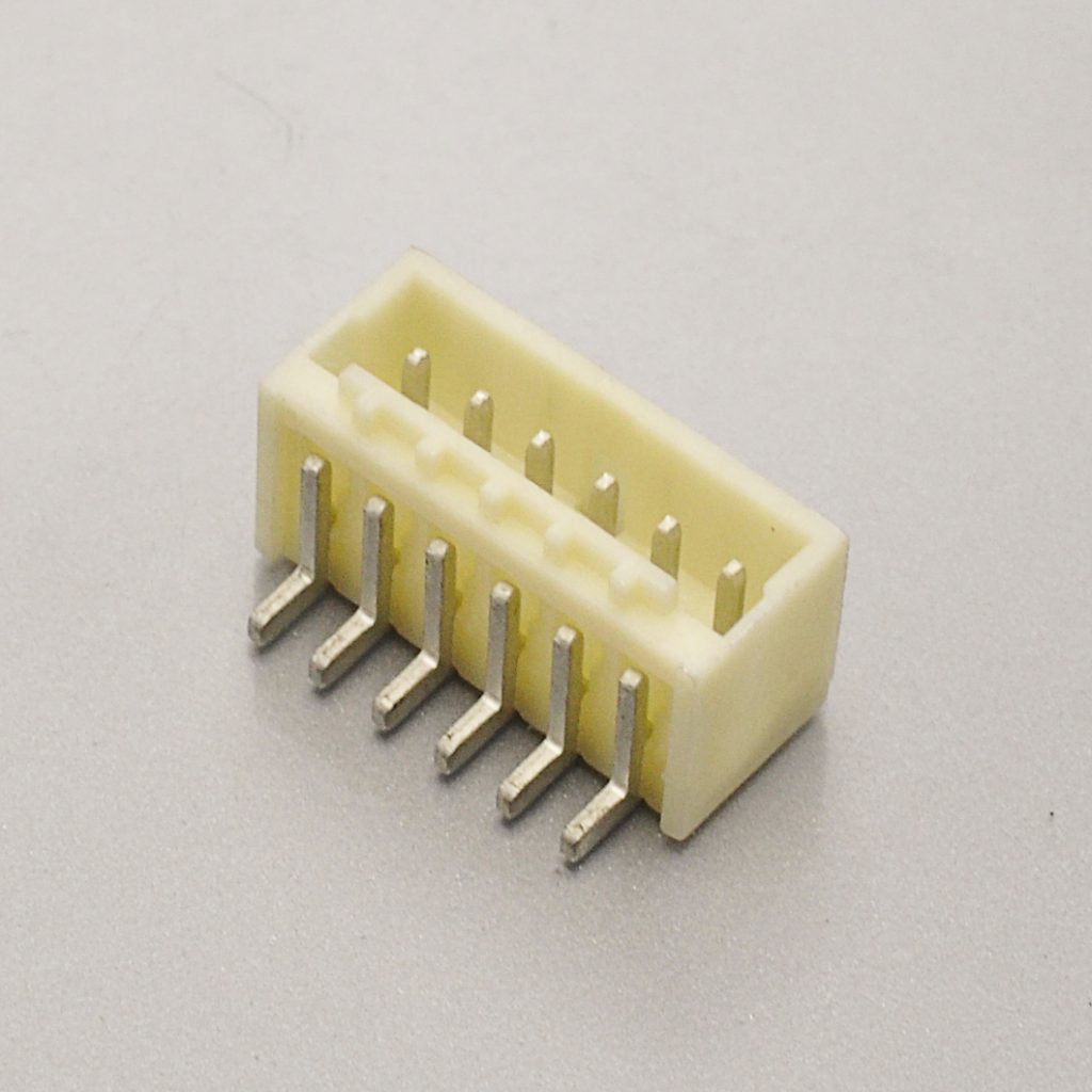
It is Molex’s 1.50mm-pitch, single-row, wire-to-board connector system, documented as saving 30% of the space of a 2.00mm-pitch wire-to-board connector at the same circuit count. It is a crimp-style system with three functional pieces: a crimp terminal, a receptacle housing and a PCB header. Molex publishes it in vertical and right-angle orientations across 2 to 15 circuits, and positions it for compact consumer devices, vehicles, appliances, industrial equipment and medical equipment.
Three design choices define it:
- A friction lock with polarization keys. Molex states the combination ensures connectors are mated in the correct orientation, which helps prevent failures due to incorrect connections. There is no separate latch to release — retention comes from friction between the mated halves, and the keys prevent a reversed or offset mate.
- A spring-box terminal. Molex describes a spring-box-shaped terminal with an SMT-type plug, designed to facilitate efficient automatic assembly. KONNRA describes the same geometry from the other side: a box-type contact plate with two inward-facing grooves that let the contacts grip the plug pins — two contact points rather than one.
- A 1.50mm pitch and a very small profile. Molex’s stated benefit is space: the friction lock mechanism, the “no nail function”, the 1.50mm fine-pitch design and a very small profile in height and length. The “no nail” detail matters — fitting nails would point at a different family.
Documented series parameters:
- 1.50mm pitch, single row, 2 to 15 circuits, wire-to-board
- 250V AC (RMS)/DC allowable voltage
- Rated current per wire gauge: 2.5A at AWG #24, 2.0A at #26, 1.5A at #28 and #30
- Reference derating table by gauge and circuit count, up to 3.5A at 2 circuits
- 500V AC (RMS) one-minute dielectric withstanding voltage, no breakdown or flashover
- 1000MΩ minimum insulation resistance
- 20mΩ maximum contact resistance — 5mΩ max on the crimped portion, 40mΩ max after environmental exposure
- −55°C to +105°C, including terminal temperature rise
- 30°C maximum temperature rise, to UL498
- 10-cycle durability on gold-plated parts
- Applicable wire AWG #24 to #30, machine insulation window φ0.70 to 1.15mm
- SMT and through-hole headers, vertical and right-angle, in Nylon and LCP body materials
- Pick-and-place cap option on some SMT headers, cap retention 0.49N (50gf) minimum
- UL File E29179 Vol.10 and CSA File LR 19980-367; RoHS compliant, and Molex lists the family as not low-halogen
The names that are not the same connector
These names get mixed up constantly, and only one of them is the 1.50mm Pico-SPOX. Working from Molex’s own wire-to-board connector listing:
- Pico-SPOX — the 1.50mm wire-to-board system. This is the family “MX1.5” refers to. Up to 3.5A at AWG #24 as a family figure, 250V AC RMS/DC, 30 to 24 AWG. Second source: KR1500.
- Mini-SPOX — a separate, larger 2.50mm wire-to-board family listed by Molex alongside Pico-SPOX. Up to 3.0A, 28 to 22 AWG, through-hole.
- SPOX — the original SPOX name belongs to the 2.50mm / 2.54mm pitch class. It is not a 1.50mm connector.
- “Micro SPOX” — appears in distributor listings but does not appear as a Molex product family on Molex’s own listing. Treat the label as unverified.
- PicoBlade — Molex’s 1.25mm wire-to-board and wire-to-wire system. A different pitch and a different family. Second sources: KR1250 (wire-to-board) and KR1251 (wire-to-wire).
- CLIK-Mate — Molex’s positive-latch system with an audible click, offered at 1.25, 1.50 and 2.00mm. Up to 4.0A. Second source: KR1507.
- Pico-Clasp — Molex’s 1.00mm wire-to-board system. Up to 2.0A, up to 100V.
- Micro-Lock Plus — Molex’s enhanced-locking system, also offered at 1.25, 1.50 and 2.00mm. Up to 4.7A.
Four things this list settles.
Do not conflate Pico-SPOX with PicoBlade. PicoBlade is 1.25mm, and although Molex’s family summary page quotes it at “up to 3.0A / up to 250V”, Molex’s own product specification for the PicoBlade receptacle system states 1.0A and 125V. That is a general lesson for this whole sub-2mm class: the family page and the product specification are different documents, and the specification is the one to quote.
The second-source numbering keeps them apart, and it is worth reading carefully. KR1501 is the JST ZH 1.5mm equivalent — a different product on a nominally similar pitch, and not interchangeable with a Pico-SPOX. KR1507 is the Molex CLIK-Mate equivalent — single row 3A/100V and dual row 1.5A/100V, a positive-latch system. Neither is a KR1500. Beyond that, note the voltage difference: Molex rates CLIK-Mate at “up to 250V” on its family page, while the KR1507 figures are documented at 100V. If your circuit runs above 100V, that is the number to settle first.
CLIK-Mate is a different conversation, not a substitution. It is a positive-latch system that Molex positions for blind mating and for assembly lines where the operator cannot see the connector seat. That is a functional upgrade: it changes the header envelope, the mating force and the harness-side housing. If your drawing specifies CLIK-Mate, cross-referencing to KR1507 is right; if it specifies Pico-SPOX, do not substitute a latch series without re-validating the layout.
“Micro SPOX” should not be quoted without verification. No Molex family of that name appears on Molex’s own listing. Confirm the pitch and the series number on the manufacturer’s documentation before you cross-reference a part described that way.
Rule of thumb: on any Molex sub-2mm connector, confirm the series number on the drawing before cross-referencing — not just the pitch. Molex runs multiple non-mating systems at 1.50mm, and Pico-SPOX is only one of them.
Retention is where the two documents diverge — by a factor of five
This is the single largest mechanical disagreement on the series, and it is worth leading with because it is the opposite of what most people expect. On this connector the documents agree about current, voltage, contact resistance, insulation resistance and temperature rise; they disagree most about retention.
Both documents publish a force table by circuit count, in kilogram-force on the KONNRA side and newtons with a kgf equivalent on the Molex side:
- 2 circuits — Molex 9.8N (1.0 kgf) minimum; KONNRA 0.2 kgf (2.0N) minimum
- 5 circuits — Molex 9.8N (1.0 kgf); KONNRA 0.5 kgf (4.9N)
- 8 circuits — Molex 15N (1.5 kgf); KONNRA 0.8 kgf (7.8N)
- 10 circuits — Molex 15N (1.5 kgf); KONNRA 1.0 kgf (9.8N)
- 15 circuits — Molex not documented in the material reviewed; KONNRA 1.5 kgf (14.7N)
At 2 circuits those differ by roughly a factor of five.
The insertion forces, by contrast, track each other closely. KONNRA specifies 2.50 kgf (24.5N) maximum at 2 circuits, rising to 7.00 kgf (68.6N) at 15 circuits; Molex specifies 25N (2.5 kgf) maximum at 2 circuits and 54N (5.5 kgf) at 8 circuits. So the divergence is specifically in retention, not in mating effort.
Why that matters more here than on most connectors: the friction lock is the only retention mechanism on a Pico-SPOX. There is no latch to share the load, and there are no nails. A withdrawal minimum of 0.2 kgf (2.0N) at 2 circuits keeps a mated pair together — it does not carry a cable load.
Practical consequence. Size the circuit count against the force table, not against the drawing. Test withdrawal force on your own samples rather than inferring it from either document, and provide a cable tie or a strain-relief feature on the harness. The correct retention answer on this family is mechanical, on the harness side.

The current rating is a ladder, and only one side publishes it that way
Molex’s headline figure and Molex’s specification are not the same thing on this connector, and neither is the second source’s.
Level 1 — the allowable current, by wire size. Molex’s product specification states it one row per gauge: 2.5A at AWG #24, 2.0A at #26, 1.5A at #28 and 1.5A at #30, all with an insulation O.D. of φ0.70–1.15mm.
Level 2 — the reference derating table, by gauge and circuit count. Molex publishes this separately and marks it as reference data: at AWG #24, 3.5A at 2 circuits falling to 2.5A at 15 circuits; at AWG #30, 2.5A at 2 circuits falling to 1.5A at 15 circuits. Molex’s stated conditions matter as much as the numbers: values are for reference only, deratings assume not exceeding a 30°C temperature rise, temperature rise is measured in the barrel area of the crimp terminal, the data is for all circuits powered, and — the line that matters in practice — PCB trace design can greatly affect temperature rise results.
Level 3 — the headline. Molex’s product page and its wire-to-board family listing both quote the family as “up to 3.5A.” That figure is real, and it is also the top of the ladder: 3.5A is a 2-circuit, AWG #24, reference-derating number at a 30°C rise. It is not the rating for your 12-circuit connector on AWG #28.
What the second source publishes, and where it gets thin. The KR1500 product specification states the rated current as 2.5A (24 AWG) — matching Molex exactly at that one gauge. But the KONNRA web specification table presents a flat 2.5A with no gauge qualifier, and the KONNRA web advantages text states a “system rating of 3.0 A.” Three numbers, from two pages of the same supplier, for the same series.
Two consequences follow:
- At AWG #24 the two companies agree at 2.5A. Nothing to resolve.
- Below AWG #24 the second source publishes no ladder. A design drawing that reads “2.5A” and a harness built on AWG #28 has no margin: Molex’s allowable current at that gauge is 1.5A. The flat 2.5A is 67% optimistic at AWG #28.
And a warning about the derating table itself. The 3.5A at 2 circuits is real, and it is also the most misquoted number on this connector. It is reference data for a 30°C temperature rise with all circuits powered on a specific test board — not a rating, and not independent of your layout. Molex says so in the specification. If your design needs more than the 2.5A allowable at AWG #24, the number to work from is your own temperature-rise test on your own board.
One more inconsistency, inside Molex’s own documents. The current rating quoted in the Molex Pico-SPOX summary datasheet is not the same for all four headers: it lists 2.5A max (AWG #24) for the 78047 / 78048 LCP headers and 3.5A max (AWG #24) for the 87437 / 87438 Nylon headers. The product specification’s per-gauge ratings — 2.5A at #24 — are the conservative set. That is precisely why the gauge-specific ladder, not the family headline, should be the one you work from.
Eight more differences to verify before you sign off
Beyond the current ladder and the withdrawal force, these are the places the two documents do not say the same thing — or where one of them says nothing at all.
1. The dielectric withstanding voltage is correct, and both sides agree at 500V AC. This is worth stating plainly, because the suspicion is reasonable and it is the one parameter people assume is wrong. KONNRA’s page carries a 250V figure and a withstanding-voltage row — and 250V is also the rated voltage, which would be a red flag if the withstanding field had been filled in with the rating by mistake. It has not been. KONNRA’s General Specification table states “Withstanding Voltage: 500V AC/minute“, the Overview text repeats it, and product specification PS-KR1500-01 §5.3 states: apply 500V AC for 1 minute between adjacent terminal or ground — No Breakdown and Flashover. Molex’s PS-87437-001-001 §5-1-3 states: apply 500V AC (rms) for 1 minute between adjacent terminal or ground — No Damage on function. Same test potential, same duration, same pass criterion. The 250V is the working voltage and the 500V is the proof test, and the KR1500 documentation carries both correctly. Record both, and do not swap them on a drawing.
2. The operating temperature range is 15°C narrower at the cold end on the second-source side. Molex documents −55°C to +105°C in both the tin-plating and gold-plating specifications, and runs its cold-resistance test at −55±3°C for 96 hours. KONNRA documents −40°C to +105°C and runs its cold test at −40±2°C for 96 hours. The hot end matches; the cold end does not. If your product is qualified to −55°C, the KR1500 as documented does not cover it — and this is a specification gap, not a test-report gap.
3. Durability runs the other way: 10 cycles on the Molex side, 30 cycles on the KONNRA side. Molex specifies 10 cycles durability (gold-plated) and a repeated insertion/withdrawal test of 10 cycles, with the “after 10X durability” condition appearing as a distinct column in its own force table. KONNRA’s product specification §7.1 specifies 30 cycles at no more than 10 cycles per minute, referenced to EIA-364-09C. A threefold claim against the original is a claim to verify rather than an equivalence to assume — the reference standards differ, so the two numbers are not directly comparable. Note also that the KONNRA web page publishes no cycle count at all; the 30-cycle figure exists only in the specification PDF, which is the more complete document. In practice, design so this connector is not the one cycled in service.
4. The insulation resistance disagrees with itself on the second-source page, but the authoritative document agrees with Molex. The KONNRA web specification table states 1000MΩ min, and the product specification §5.2 states 1000 Megohms Min. — identical to Molex’s 1000MΩ min. The outlier is the web Overview prose, which says “high insulation resistance (min. 100MΩ)”. Note also that KONNRA’s own product specification §7.7 requires only 100 Megohms Min. after the humidity test — a separate, post-conditioning requirement that is not the same as the base specification. Quote 1000MΩ for the unmated baseline, and 100MΩ as the post-humidity floor if that is the figure your programme needs.
5. The applicable wire range stops at AWG #28 on the KONNRA side. Molex’s applicable wire range is AWG #24 to #30, split across two terminal families. KONNRA’s product specification §4 states applicable wire AWG 24# to 28#, and the web entry states 24-28 AWG. AWG #30 is outside the published KR1500 range. AWG #30 is the finest and least current-capable gauge in the family — 1.5A, and a 4.9N (0.5 kgf) minimum crimp pull-out force on the Molex side — so the practical risk is low, but if your harness uses #30, raise it rather than assume it.
6. The insulation diameter window is a single band on one side and two windows on the other. Molex’s machine specification allows φ0.70 to 1.15mm, but its two terminal families are individually qualified at 0.70–1.00mm (the #30–26 terminal) and 0.95–1.20mm (the #26–24 terminal). KONNRA publishes 0.7 to 1.1mm as a single band across the series. A cable with 0.9mm insulation passes the Molex machine window and sits outside the Molex lighter-wire terminal’s window, while sitting inside KONNRA’s band — so the same wire can be acceptable on one side and not the other, depending on which terminal is fitted. Check both ends against the actual terminal, not against the family figure.
7. Mounting: the second source documents SMT only. KONNRA’s product specification labels its wafers SMT 180° (straight) and SMT 90° (right angle), while Molex lists both SMT and through-hole headers in the Pico-SPOX ordering table. If your design needs a through-hole header, that configuration is not documented for the KR1500.
8. Agency approvals: the file numbers are on one side only. Molex cites UL File E29179 Vol.10 and CSA File LR 19980-367 in the product specification, while the KONNRA product specification carries no agency file numbers. Worth requesting if your qualification requires UL recognised status for the specific part.
The environmental test data is not interchangeable
Both documents use 40mΩ max contact resistance as the acceptance limit after environmental exposure — but the exposures are not the same, and several of the gaps are large enough that the two cannot stand in for each other as evidence.
- Heat resistance: Molex 105±2°C for 168 hours; KONNRA 105±2°C for 96 hours
- Cold resistance: Molex −55±3°C for 96 hours; KONNRA −40±2°C for 96 hours
- Humidity: Molex 85±2°C / 85±3% RH for 168 hours; KONNRA 40±2°C / 90–95% RH for 96 hours
- Temperature cycling: Molex −55°C / +105°C, 2 hours each, 10 cycles; KONNRA −40°C / +105°C, 30 minutes each, 5 cycles
- Salt spray: Molex 48±4 hours; KONNRA 24 hours — both at 35±2°C, 5±1% NaCl
- Vibration: Molex 1.52mm P-P, 10–55–10Hz, 2 hours per axis; KONNRA 1.5mm P-P, same sweep, 2 hours per axis
- Mechanical shock: Molex 490 m/s² (50G), 11ms, 18 shocks; KONNRA 490 m/s² (50G), 3 strokes per axis
- Solderability: both at 245±5°C — Molex 5±0.5 seconds, KONNRA 3±0.5 seconds
The humidity test is the widest gap. 85°C / 85% RH is a materially harsher exposure than 40°C / 90–95% RH, and the two are not interchangeable as evidence. If your qualification calls up an 85/85 humidity test, the KR1500 document does not evidence it as written. That belongs on the enquiry, not in a surprise at qualification.
Design and process notes that account for most field problems
Molex publishes a detailed set of constraints and test conditions for this series, and they describe the failure modes the product is known to have. Use them as your review list; the corresponding KONNRA document does not repeat all of them.
Clean up the derating thinking first. The published table assumes all circuits powered — the worst case — measured in the barrel area of the crimp terminal, at a 30°C temperature rise, on a specific test board, and Molex states plainly that PCB trace design can greatly affect temperature rise results. A design that passes on two circuits will not necessarily pass on fifteen. Check the sum of current across circuits, not just the per-circuit figure.
Respect the 30°C maximum temperature rise. Both documents specify 30°C max — Molex referencing UL498, KONNRA referencing EIA-364-70B — and both include terminal temperature rise inside the operating temperature range.
Tie the cable down; do not hang the harness from the connector. With no positive latch, the correct retention answer is a cable tie or a strain-relief feature on the harness, not the friction lock. At 2 circuits the withdrawal minimum is specified at 0.2 kgf (2.0N) on the second-source document. A friction lock of that order keeps a mated pair together; it does not carry a cable load.
Check the polarity key engagement as part of the build instruction. Both the Molex and KONNRA descriptions rely on polarization keys to prevent mis-mating. A key that is not engaged means the housing is not seated, and the friction lock alone will not hold it.
Watch the solder-joint stress on SMT headers. A 1.50mm-pitch SMT header carries real insertion and withdrawal forces — up to 7.0 kgf (68.6N) insertion at 15 circuits on the KONNRA document. Solder-tab retention is specified at 9.8N (1.0 kgf) minimum on both sides, which is the number to design against if the harness will be pulled.
Do not reflow past the documented profile. KONNRA’s product specification §9.0 gives a 255±5°C peak for 5–10 seconds, a minimum of 230°C, and a 150–200°C preheat, and states that the condition changes with the soldering device and the PCB. Molex qualifies its SMT headers to three IR reflow passes, and allows 350±5°C for 5 seconds maximum with a soldering iron.
Plan a new housing after terminal extraction. Extracting a crimp terminal deforms the housing lance, which is the feature that holds the terminal. Fitting a new housing after extraction is the safe assumption on this family, on both the Molex and the KONNRA side.
Decide the plating before you qualify, not after. On this interface the finish sits in the part number — Molex offers pre-tin, 0.100µm minimum gold and 1.000µm minimum gold as distinct options, and KONNRA offers tin and gold terminal part numbers. A BOM line reading “gold plated” does not record which one you qualified.
And the placement question, if the board runs through a standard SMT line. Molex offers SMT headers with a pick-and-place cap, specifying cap retention at 0.49N (50gf) minimum. KONNRA does not document an equivalent placement feature. If your nozzle needs a flat top, raise it before tooling.
What the Pico-SPOX is not for. At a rated 2.5A at AWG #24 — and only 1.5A at AWG #28 and #30 — it is a small-power and signal interface, not a power connector. And although Molex cites a “no nail function”, a 1.50mm-pitch friction-lock pair is not a board-to-board retention system: do not design a service procedure or a cable route that loads the mated pair.
Components, part numbers, and what the family name hides
The KR1500 is specified as nine separately orderable components — six wafers, two housings and a terminal — which is what lets the same series serve straight and right-angle SMT designs with and without an additional buckle feature:
- Right Angle Wafer — SMT 90°
- Right Angle Wafer Have Buckle
- Right Angle Wafer Have Buckle B
- Straight Wafer — SMT 180°
- Straight Wafer Have Buckle
- Straight Wafer Have Buckle B
- Housing — the cable-side receptacle
- Housing Have Buckle
- Terminal — crimp contact for AWG #24 to #28
Two notes on the wafer range. KONNRA documents the wafer base as LCP, UL94 V-0, with brass contacts and a brass solder tab — and does not publish a separate Nylon-header option. So if your layout was qualified against a Molex Nylon header (87437 / 87438) rather than an LCP one (78047 / 78048), name the body material when you enquire. Second, the “Have Buckle” and “Have Buckle B” variants are KONNRA additions that do not appear as distinct entries in Molex’s Pico-SPOX ordering table — if your design relies on the plain friction lock, order the plain wafer and keep the buckle variants for the applications that need extra retention.

The internal part numbers carry more information than the family name. The KONNRA product specification assigns part numbers by functional group:
- Housing —
H150001****01AandH150001****02A - Terminal —
T15000PG0101A(gold) andT15000PT0101A(tin) - Wafer —
C1500RS1*********RA(right angle) andC1500VS1*********RA(straight)
Note the naming logic: RS is right angle, VS is straight, and the PG / PT suffix distinguishes gold from tin plating. That is the check to run when a BOM line reads only “KR1500 terminal” — the plating is in the part number, not the family name.
On the Molex side the terminal splits four ways, which the family name also hides. Molex’s Pico-SPOX terminal series 87421 covers two wire ranges in two finishes, all in phosphor bronze:
874210100— AWG #30–26, pre-plated tin 2.540µm, insulation O.D. 0.70–1.00mm — lighter wire, tin-terminated interface874210102— AWG #30–26, gold 0.100µm min with a 1.270µm nickel barrier, 1.00mm max — lighter wire, low-level-signal interface874210000— AWG #26–24, tin 2.540µm, 0.95–1.20mm — heavier wire, tin-terminated interface874210002— AWG #26–24, gold 1.000µm min, 0.95–1.20mm — heavier wire, specified gold thickness
The two families overlap at AWG #26, and there the plating spec decides as much as the wire. All four terminals carry the same headline ratings — 2.5A, 250V, 10 mating cycles — so the selection question is really two independent questions: which gauge family, and which finish. Note also that the gold thickness itself is not one number: the lighter-wire gold terminal is specified at 0.100µm minimum and the heavier-wire one at 1.000µm minimum, a tenfold difference. A BOM line reading simply “gold plated” records none of that.
And on the KONNRA side, two things follow from having one terminal. The terminal is documented as “Tin/Gold Plated Over Nickel” in the product specification, split into the PT (tin) and PG (gold) part numbers — so the staged gold thickness is not documented, and the insulation diameter window is published as a single 0.7–1.1mm band rather than the two terminal-specific windows Molex uses. If your qualification names a gold thickness, or your cable insulation sits near a window boundary, both are worth raising on the enquiry.
On the header body material. Molex’s four headers split by orientation and body: 87437 (vertical, Nylon), 87438 (right-angle, Nylon), 78047 (vertical, LCP), 78048 (right-angle, LCP). The Nylon headers are the mainstream SMT parts and pick-and-place cap variants exist for them; the LCP parts are the higher-temperature body material. As noted above, the current rating in Molex’s summary datasheet is not identical across the four, which is one more reason to work from the gauge-specific table. KONNRA documents wafers in LCP only, in straight (SMT 180°) and right-angle (SMT 90°). If your board profile or reflow process was qualified against a specific Molex body material, name that material on the enquiry.
Series documentation, and one caveat about it:
- KR1500 series engineering drawing — vector PDF artwork
- KR1500 product specification —
PS-KR1500-01, rev A1, issued 2022/2/26 - KR1500 package specification
The engineering drawing is published as vector PDF artwork: dimensional values must be read from the drawing itself and are not exposed as machine-readable text. Ask for the specific circuit count and orientation you intend to order, so the correct sheet is supplied.
Cable assembly and crimp settings
The same interface is built into harness assemblies in the standard configurations:
- Single-headed — housing on one end, bare wire leads on the other; a pigtail from a board header to a termination point
- Same-side-head — housing on both ends, same orientation; extending a run between two boards
- Reverse-side-head — housing on both ends, reversed orientation; routing through a fold or hinge
- Adapter and transition cables — KR1500 on one end, another interface on the other, for example Pico-SPOX to a 1.50mm JST ZH interface or to a 1.00mm interface
- Harness with buckle-side housing — the KR1500 housing with the buckle feature, paired with the matching wafer
Crimp settings are gauge-specific rather than one setting for the family. KONNRA’s product specification §6.5 publishes the crimp dimensions per gauge, and they are more detailed than most connector datasheets — they are the numbers your harness house should be crimping to:
- AWG #24 — conductor crimp height 0.70±0.05mm, insulation crimp height 1.45mm max, crimp strength 3.63 kgf min, strip length 1.2–1.6mm
- AWG #26 — 0.65±0.05mm, 1.40mm, 2.27 kgf, 1.2–1.6mm
- AWG #28 — 0.55±0.05mm, 1.25mm, 1.36 kgf, 1.2–1.6mm
with a conductor crimp width of 0.9–1.0mm and an insulation crimp width of 1.15mm max. Note that KONNRA’s minimum crimp strength is higher than Molex’s crimp pull-out minimum at the same gauges (3.63 vs 3.0 kgf at #24, 2.27 vs 2.0 kgf at #26, 1.36 vs 1.0 kgf at #28) — but the two are tested to different standards, so treat that as encouraging rather than equivalent. Molex’s own crimp pull-out minima across the four gauges are 29.4N (3.0 kgf) at #24, 19.6N (2.0 kgf) at #26, 9.8N (1.0 kgf) at #28 and 4.9N (0.5 kgf) at #30.
And if your harness house needs the original crimp standard, it is not in the main document. Molex publishes a separate application specification per series rather than folding the crimp process into the product specification — the product specification for the 87437 header series points to application specification 874370000-AS. That is where the original crimp standard lives.
Connector lead time is typically 2–3 weeks; wiring harness lead time is typically 3–4 weeks. Key materials are prestocked.
Sourcing questions procurement teams ask
“Can you be a second source without changing our design?” That is what a documented cross-reference is for. The KR1500 is specified against the Molex Pico-SPOX 1.50mm system at component level — housing, terminal and six wafer variants — with matching 1.50mm pitch, 250V rating, 500V AC withstanding voltage, 20mΩ contact resistance, 1000MΩ insulation resistance, 30°C maximum temperature rise and a two-groove spring-box contact. Equivalence is confirmed against your specific part number, because wire gauge, orientation, plating and circuit count all change the answer.
“What are your lead times?” Connector production lead time is typically 2–3 weeks. Wiring harness lead time is typically 3–4 weeks. Key materials are prestocked.
“How long for samples?” Complete connector set samples can be delivered within 45 days. Where you need to validate withdrawal force or crimp pull-out before committing — the two figures where the documents differ most — sample harnesses can be supplied from the same process used in production.
“What qualifications do you hold?” ISO9001, ISO14001, IATF16949, ISO45001:2018, ISO13485, IPC620, and UL product and operational safety certifications. Automotive-grade series additionally hold LV214 and US CAR-2.
“How do we know the parts match your documentation?” A CNAS-accredited laboratory with 45+ sets of precision testing instruments, with dimensional and electrical verification data available on request. 95% of production processes carry full-line intelligent visual CCD inspection; automotive series receive 100% CCD inspection.
“Are you a manufacturer or a trader?” A manufacturer. Dongguan Konnra Electronics Co., Ltd., founded 2004, with in-house mould design, injection moulding, stamping, assembly and inspection — so the connector and the cable assembly come from one quality system.
“What volumes can you support?” KONNRA reported 2025 sales of RMB 310 million, with connectors at 60% and wiring harnesses at 40% of the product mix, across four production bases with automation coverage exceeding 95%.
“Who else buys from you?” KONNRA states that it serves global cooperative clients including BYD, Volkswagen and DJI.
“What about the gaps in your documentation?” Ask for them directly. The withdrawal force at low circuit counts, the gold plating thickness, AWG #30 coverage, the pick-and-place feature and the agency file numbers are the five items where the second-source documentation is thinner than Molex’s. Requesting test data on those is a reasonable enquiry, not an awkward one.
Engineer’s pre-release checklist
Run this before you release a drawing for a Pico-SPOX-family connector.
- Pitch and series confirmed, not assumed. 1.50mm is Molex Pico-SPOX, CLIK-Mate or Micro-Lock Plus — plus the non-mating JST ZH class. Confirm the series number, not just the pitch.
- The part is a Pico-SPOX and not a PicoBlade. PicoBlade is 1.25mm; the equivalents are KR1250 and KR1251, not KR1500.
- The second source is KR1500 — not KR1501 and not KR1507. KR1501 is the JST ZH 1.5 equivalent; KR1507 is the Molex CLIK-Mate equivalent.
- Wire gauge confirmed inside the range both sides cover — Molex documents AWG #24 to #30; the published KR1500 range is AWG #24 to #28. If you are on AWG #30, raise it.
- Current checked per gauge, not per family — 2.5A at AWG #24, 2.0A at #26, 1.5A at #28 and #30. A flat 2.5A on an AWG #28 harness is 67% optimistic.
- The second-source page’s own three current figures reconciled — 2.5A in the specification table, 2.5A in the Overview, “3.0A system rating” in the advantages text. Pick one, in writing.
- Dielectric withstanding voltage confirmed at 500V AC for one minute — this one agrees on both sides, so no action, but record it, because 250V is the rated voltage and the two must not be swapped on a drawing.
- Insulation resistance quoted from the right place — 1000MΩ min is the base figure on both sides; 100MΩ appears in the second-source Overview prose and again as the post-humidity floor in its product specification.
- Derating position established from your own board, not the datasheet table. The 3.5A-at-2-circuits figure is reference data for a 30°C rise with all circuits powered on a test board, and Molex states that PCB trace design greatly affects the result.
- Sum of current across circuits checked against the maximum allowable, not just the per-circuit figure.
- Insulation outside diameter confirmed against the actual terminal — Molex’s machine window is φ0.70–1.15mm, but its lighter-wire terminal is qualified at 0.70–1.00mm; KONNRA publishes 0.7–1.1mm.
- Plating finish and thickness specified. Molex offers tin, 0.100µm min gold and 1.000µm min gold, with the finish encoded in the terminal part number. KONNRA documents no thickness.
- Durability considered — Molex specifies 10 cycles; the KR1500 product specification specifies 30 cycles. Design so this connector is not the one cycled in service.
- Retention sized against reality. Molex specifies a 9.8N (1.0 kgf) minimum withdrawal at 2 circuits; the KONNRA specification gives 0.2 kgf (2.0N) at the same circuit count. Test it, do not infer it.
- Cable tie or strain relief provided, because a friction lock retains the pair but does not carry a cable load.
- Operating temperature range checked at the cold end — Molex −55°C, KONNRA −40°C.
- Environmental test severities matched to your qualification — heat 168h vs 96h, humidity 85/85 vs 40°C/90–95% RH, salt spray 48h vs 24h, thermal cycling 10 cycles vs 5.
- Temperature rise checked against the 30°C maximum, including terminal temperature rise inside the operating range.
- Wafer orientation and mounting type matched to your layout — SMT 180° or SMT 90°, with or without the buckle feature, and confirm the pick-and-place requirement if the board runs through an SMT line.
- Agency approval requirement stated. Molex cites UL File E29179 Vol.10 and CSA LR 19980-367; the KONNRA product specification lists no agency file numbers.
How to identify whether your connector is a Pico-SPOX
If you are holding a connector and a drawing you cannot match, work through these in order.
- Measure the pitch. 1.50mm points at Molex Pico-SPOX, CLIK-Mate or Micro-Lock Plus — or at the JST ZH class. 1.25mm points at PicoBlade; 1.20mm at Pico-EZmate; 1.00mm at Pico-Clasp.
- Count the positions. The Pico-SPOX is documented from 2 to 15 circuits. More than 15 is not a standard Pico-SPOX.
- Look at the contact geometry. A spring-box terminal with two inward-facing grooves is the Pico-SPOX signature. A single-point contact at this pitch indicates a different series.
- Check the retention mechanism. Pico-SPOX is a friction lock with polarization keys — no separate latch to release. If there is a positive latch that clicks, you are holding a CLIK-Mate (KR1507), not a Pico-SPOX.
- Look for a “no nail” body. Molex lists the Pico-SPOX as having no nail function. Fitting nails would point at a different family.
- Check the number of functional pieces. A Pico-SPOX assembly is a crimp terminal + receptacle housing + PCB header — three pieces, with the harness end crimped rather than soldered.
- Read the part number if there is one.
87439is the receptacle housing,87421the crimp terminal,87437/87438the Nylon headers and78047/78048the LCP headers. - Check the header top. A flat pick-and-place cap is consistent with an SMT Pico-SPOX header intended for automated placement.
If you are still unsure, photograph the connector next to a ruler, with any part number markings visible. At this pitch the measurement identifies the family; the part number identifies the variant.
Getting a cross-reference check on your MX1.5 part number
Most MX1.5 enquiries stall on the same thing: the buyer is not sure what information the supplier needs, so the enquiry never gets sent. This is the complete list.
Send:
- The original part number, if you have it — a housing such as
87439****, a terminal such as874210000, or a header such as87437**** - Circuit count — the range is 2 to 15
- Wire gauge, and specifically whether it is AWG #28 or #30. Molex’s allowable current is 1.5A at both of those gauges, while the second-source web page shows a flat 2.5A, so those two gauges need to be raised explicitly
- Insulation outside diameter, not just the gauge. Molex allows φ0.70–1.15mm in the machine specification, but only 0.70–1.00mm on the lighter-wire terminal; KONNRA publishes 0.7–1.1mm
- Plating finish required — tin or gold, and if gold, at what thickness
- Mounting and orientation — straight or right-angle, and confirm whether you need through-hole
- Whether the design needs a buckle variant — the “Have Buckle” and “Have Buckle B” wafers are second-source additions, so say which one your retention strategy relies on
- Your load current per circuit and the number of circuits carrying it, so the gauge-specific allowable current and the derating position can be settled rather than assumed
- Minimum operating temperature, if your product goes below −40°C
- Application and annual volume
- A drawing or photo if the part number is unreadable or the design has been reverse-engineered
When you send a part number, four things get confirmed against Molex’s own documentation: the terminal that matches your wire gauge and insulation diameter, the plating and its thickness, the header orientation and mounting type, and whether your design needs the plain friction-lock wafer or a buckle variant. Those four are where an MX1.5 cross-reference most often goes wrong.
What you get back: a mapped KR1500 part number with the relevant product and engineering drawings, a specification comparison against your original part, and a sample and quote plan.
About KONNRA
Dongguan Konnra Electronics Co., Ltd. (brand: KONNRA) was founded in 2004 and is a National High-Tech Enterprise specialising in connector and wiring harness research, development, production and sales.
Manufacturing depth. A vertically integrated process covering precision mould design and manufacturing, automation design, precision injection moulding, stamping, assembly and CCD visual inspection, with automation coverage exceeding 95%.
Testing and validation. A CNAS-accredited laboratory with 45+ sets of precision testing instruments, and CAE analysis — contact nonlinear analysis, material nonlinear analysis, motion simulation, thermal field analysis and high-frequency analysis — performed in Ansys 2022 R1. Verification data is available on request.
Inspection coverage. Full-line intelligent visual CCD inspection covers 95% of production processes, using Mitsubishi and Panasonic PLC control systems with FA25–35mm optical lenses and 5-megapixel cameras. Automotive connector series receive 100% CCD visual inspection.
Quality systems. ISO9001, ISO14001, IATF16949, ISO45001:2018, ISO13485, IPC620, and UL product and operational safety certifications, with automotive-grade series additionally certified to LV214 and US CAR-2.
Capacity and delivery. Production bases in Dongguan Wangniudun (30,000 m², 350+ employees), Dongguan Changan (10,000 m², 150+ employees) and Hunan Daoxian (2,600 m², 100+ employees), with regional offices in Beijing, Chongqing, Hunan, Shanghai and Kunshan. Key materials are prestocked, and complete connector set samples can be delivered within 45 days. KONNRA reported 2025 sales of RMB 310 million, with connectors at 60% and wiring harnesses at 40% of the product mix, and has served global cooperative clients including BYD, Volkswagen and DJI.
Custom and joint R&D. Where a standard part does not fit — an AWG #30 path, a specific gold thickness, a non-standard harness length, a buckle variant, or a transition to another interface — KONNRA supports customer joint R&D customisation.
What to ask for:
- A quote — KR1500 pricing, MOQ and configuration options for your circuit count, orientation and wafer variant
- A sample — complete connector set samples within 45 days
- Cross-reference verification — KR1500-to-Pico-SPOX equivalence against your specific part number, including the terminal for your wire gauge and insulation diameter
- The withdrawal-force data — the parameter where the two documents differ most, and worth testing rather than inferring
- AWG #30 confirmation — this gauge is inside Molex’s range and outside the published KR1500 range
- Plating thickness data — Molex specifies 0.100µm and 1.000µm minimum gold options; KONNRA documents no thickness
- Drawings — series engineering drawing, product specification and package specification
- A vendor qualification pack — certificates, test capability summary and quality documentation
- Adapter harnesses — Pico-SPOX to a 1.50mm JST ZH interface, Pico-SPOX to a 1.00mm interface, or another interface on the far end
- A drawing review — we will flag any specification mismatch before you commit tooling
Contact KONNRA Electronics
- Phone: (86)-769-85449875
- Email: info@konnra.com
- Address: No.6 Nanchang South Road, Chijiao, Wangniudun, Dongguan, Guangdong, China
- Contact us
View the KONNRA KR1500 MX1.5 (Pico-SPOX) Connector · Molex connector alternatives
Sources and method. Every figure in this article is traceable to a named document. Molex Pico-SPOX figures are taken from three Molex publications: PS-87437-001-001 Rev G, Pico-SPOX 1.5mm Pitch Wire to Board Single Row Connectors (Tin-Plating) Product Specification; 2027051000-PS-000 Rev B, the gold-plating product specification; and Molex’s published product and part-list data for the 87421, 87437 and 87439 series together with the Pico-SPOX connector-family datasheet. KONNRA KR1500 figures are taken from the KR1500 product page and the KR1500 Product Specification PS-KR1500-01 (rev A1, issued 2022/2/26). The neighbouring-family rows — Mini-SPOX, SPOX, “Micro SPOX”, PicoBlade, CLIK-Mate, Pico-Clasp and Micro-Lock Plus — come from Molex’s published wire-to-board connector listing. Molex figures and KONNRA figures are placed side by side without reconciliation: where the two disagree, the disagreement is stated rather than averaged, and where one side is silent the cell reads “not documented” and the gap is named. Figures that could not be traced to a source document are flagged for confirmation rather than estimated, and the KR1500 engineering drawing is published as vector artwork whose dimensional values are not exposed as machine-readable text.
https://konnra.com/molex-pico-spox-connector-complete-guide/
Dongguan Konnra Electronics Co., Ltd