One pitch, four Molex systems, two documents that disagree — and what to verify before you second-source a 1.25mm board-in interface.
Two facts decide whether a “Molex MX1.25 board-in” project succeeds, and neither of them is a datasheet number.
The first is architectural. A board-in connection has no board header at all — no wafer, no pin block soldered to the PCB, no second solder joint. The crimp housing is the component mounted at the board, and the crimped wire terminals load into it from the wire side. Molex states the intent plainly: board-in connectors “meet the requirements of a cost-effective easy-to-assemble connection that does not need to be unmated on at least one end.” Read that as a test. If your design shows a board-mounted header that a wire-side housing plugs onto, you do not have a board-in design, and no amount of pitch matching will make the board-in cross-reference fit.
The second is uncomfortable. On the wire side of this family there are two terminals — 50061 for 28–32 AWG and 50080 for 26–28 AWG — and Molex’s part page for 50080-8000 lists the series as Obsolete, with the replacement instruction “Contact Molex”. An older distributor snapshot of the same part, dated 2013, still shows it as Active. If your drawing calls out 50080, the second-source exercise is not optional.
Here is the full system: what board-in is, why the pitch cannot identify your part, the four documentation traps, and what the architecture changes about your design.
What a board-in connector actually is
“Molex MX1.25” is trade shorthand, built from the 1.25mm pitch. On the board-in side of Molex’s catalogue it maps to the 51022 Board-in Crimp Housing and its matching male crimp terminals — and Molex’s own product name field for these parts is simply “Board-in“.
- Pitch: 1.25mm, single row
- Mating direction: vertical — the wire exits perpendicular to the board
- Housing: 51022 series, Polyester, colour Natural
- Terminals: 50061 series for AWG 28, 30, 32 · 50080 series for AWG 26, 28
- Terminal material: phosphor bronze, tin plated — minimum 0.889µm on the mating area and 0.914µm on the termination area
- Circuits: 2 to 15 by part number,
51022-0200through51022-1500 - Voltage rating: 125V maximum
- Current rating: 1.0A maximum per contact, and 0.8A at AWG 32
- Wire insulation diameter: 0.50mm to 1.00mm (50061 terminal)
- Operating temperature: −40° to +85°C (51022 housing)
- Wafer / board header: not applicable — that is the point of the architecture
- Packaging: bag for the housing, reel for the terminals
- Cross-reference equivalent: KONNRA KR1252
- Pre-crimped leads: Molex lists 797581062 and 797581063 as PicoBlade board-in pre-crimped leads used with the 51022 housing — worth knowing if your board-in side stays original Molex and only the far end is being re-sourced
Four consequences follow from the architecture, and they explain most of what makes this family different:
- There is no wafer in the bill of materials. Molex’s 51022 part pages list a housing and crimp terminals, not a header. KONNRA’s KR1252 is structured the same way — a terminal page and a housing page — and its series specification states Wafer: None. That last field is the clearest possible statement that this is a board-in part and not a wire-to-board kit.
- The piece count per connection is lower. One housing plus terminals replaces a housing, a header, and the solder joint that would otherwise carry the interface.
- Serviceability is the trade-off. Molex’s wording is that at least one end does not need to be unmated. If your design has to be plugged and unplugged repeatedly at both ends, this is the wrong family and you want the PicoBlade wire-to-board system instead.
- Mating geometry is vertical. Both the 51022 housing and the 50061 terminal are described as vertical. If your enclosure was designed around a right-angle cable exit, the interface geometry is wrong — this is not a pitch problem and cannot be fixed by matching the pitch.

One pitch, four systems: why “1.25mm” cannot identify your part
This is where cross-references fail before a single specification is compared. Molex runs at least four separate systems at 1.25mm pitch. They share the pitch and nothing else, and the trade name “MX1.25” is used loosely for all of them.
- Board-in — 51022 housing, 50061 / 50080 terminals · vertical, no wafer → KONNRA KR1252
- PicoBlade wire-to-board — 51021 housing, 50079 / 50058 terminals, plug assemblies 53047 / 53048 · vertical and right-angle, plus wire-to-wire → KONNRA KR1250 (wire-to-board) and KR1251 (wire-to-wire)
- CLIK-Mate wire-to-board — 502380 housing family · positive lock → no equivalent documented against KR1252
- PanelMate wire-to-board — 51146 housing family · ultra low profile → no equivalent documented against KR1252
Four things this settles.
First, “1.25mm” is not a part number. Board-in, PicoBlade, CLIK-Mate and PanelMate look like neighbours in a parts list, and a drawing that says “1.25mm Molex” and nothing else cannot be quoted from the pitch alone.
Second, board-in is the only one of the four with no wafer. If your drawing shows a board-mounted header plus a wire-side housing, you have a wire-to-board design and the board-in cross-reference is the wrong part.
Third, the KONNRA family splits the same way. KR1252 is the board-in branch; KR1250 and KR1251 serve the PicoBlade wire-to-board and wire-to-wire interfaces. A 1.25mm enquiry that does not say which of those three architectures it is cannot be answered from the pitch.
Fourth, locking is the other divider. Board-in parts have no separate latch to release, because at least one end is not meant to be unmated. A prominent positive lock points at a different family.
The four documentation traps
These are the ones that cause damage, in the order they tend to cause it. All four are documentation mismatches rather than electrical ones — which is exactly why they survive technical review and end up on a BOM.
1. The cross-reference target may be obsolete. Molex’s part page for 50080-8000 lists the series as Obsolete with “Replacement: Contact Molex”, and points to 50080-8100 as the loose-packaging alternative. An older distributor snapshot still shows Active. On a long-life programme, confirm what Molex currently recommends before building a second-source plan around a part on this list. And keep the sizing straight while you are there: 50080 is the 26–28 AWG terminal; 50061 is the 28–32 AWG one.
2. KONNRA’s own documentation states two different voltage ratings. The product page states 125V, its Overview paragraph says “voltage ratings up to 125V AC/DC“, and both component pages state operating voltage 125V. But the series specification PDF, PS-KR1252-01 clause 4.0, states “Rated Voltage (Max.) 50V AC/DC“. Molex publishes 125V maximum for the 50061 terminal. So two of KONNRA’s three published levels agree with Molex, and the third does not — and the third is the document an engineer is most likely to attach to a drawing. Resolve it in writing if your application runs above 50V, or if the receiving-inspection document will be the specification PDF.
3. A KONNRA row states an insulation diameter equal to the pitch. The specification PDF and both component pages state 1.00mm maximum for the applicable wire insulation O.D. The product page General Specification table states “Insulation O.D 1.25mm” — which is exactly the pitch. Molex documents 0.50mm to 1.00mm for the 50061 terminal. Three KONNRA sources say 1.00mm and one says 1.25mm; treat the 1.25mm row as a probable transcription artefact and confirm the limit against your actual cable.
4. The KONNRA terminal page names the wrong half of the Molex terminal pair. The housing page names Molex 51022, which is correct — 51022 is the board-in housing. But the terminal page names the Molex 50080 series while documenting that terminal for AWG 28# to 32#. In Molex’s catalogue, 28–32 AWG is the 50061 range; 50080 is the 26–28 AWG part. So the component page points at the wrong half of the pair for its own published wire range. This is the same conversation as the obsolescence question — resolve both together.
Where the two sides genuinely agree — and the one row that is right here
Worth stating explicitly, because on a cross-reference agreement is not a given:
- Contact resistance: 20mΩ max — both sides
- Insulation resistance: 100MΩ min — both sides
- Pitch, single row, vertical mating direction — both sides
- Dielectric withstanding voltage: 250V AC for 1 minute — both sides
- Temperature rise: 30°C max — both sides
That dielectric row deserves a note, because on some KONNRA series it is filled in wrongly — with the connector’s rated voltage copied into the dielectric test row, making the number a factor of ten too small. Here it is not. KONNRA’s specification states 250V AC for 1 minute between adjacent terminals or between terminal and ground, with the requirement “no breakdown and flashover”, and the rated voltage on its product pages is 125V. So 250V is a genuine dielectric test value, not a mis-copied rating — and it matches the 250V AC (rms) dielectric strength test in Molex’s 1.25mm system specification.
The one caveat is document provenance: the 250V figure on the Molex side is taken from Molex’s 1.25mm PicoBlade system specification, because Molex’s board-in product specification (PS-51022-001 / PS-51022-002-001) is referenced from its part pages but the PDF itself was not retrievable when this was written. If your qualification depends on that specific document, request it directly.
Where they differ materially
Operating temperature — a 20°C difference, with no published headroom above the KONNRA claim. Molex documents −40° to +85°C for the 51022 housing. KONNRA documents −40°C to +105°C, and backs the upper figure with a heat-resistance test at 105±2°C for 96 hours. The KONNRA part is claimed over a wider window than the Molex part — but its own heat-ageing test runs at exactly 105°C, so treat the upper limit as a hard ceiling rather than a conservative claim with margin behind it. If your application runs near 105°C continuously, confirm it for your assembly.
Housing material. Molex specifies Polyester; KONNRA specifies Nylon66 (PA66) with a UL94V-0 rating and colour White against Molex’s Natural. Different polymers with different moisture uptake, dimensional behaviour under thermal cycling and reflow tolerance. If the housing sees reflow or a wash, that is a process question rather than a datasheet footnote — and note the comparison is not “rated versus unrated”: Molex’s 51022 datasheet reviewed here does not state a flammability rating at all, so this is two different materials, one of which carries a published V-0 claim.
Plating construction. Molex documents tin with stated minimum thicknesses on the mating and termination areas. KONNRA documents tin plated over nickel, with no thickness for either layer. Tin-over-nickel is a different construction from tin directly on phosphor bronze, and not equivalent in porosity or long-term contact stability. If contact finish is part of your qualification, ask for the thickness of both layers in microns.
Circuit count — 2 to 15 against 2P to 16P. Molex’s 51022 catalogue documents housings from 2 circuits (51022-0200) to 15 circuits (51022-1500). KONNRA documents 2P to 16P on both the product page and the housing page. Either KONNRA offers a 16-position housing Molex does not, or the range describes something else. Confirm the exact count before it reaches a drawing.
Mating durability — published by Molex, not by KONNRA. The 1.25mm system specification states 30 cycles for tin-plated parts. KONNRA publishes no cycle count for KR1252. On a board-in connector the question is narrower than on a mating pair — the interface is not designed for repeated unmating — but if the housing will be loaded and re-loaded during assembly rework, ask for a figure.
Standards. Molex references UL File E29179 through the 1.25mm system specification. The KONNRA housing and terminal pages list UL file E482542. Different files — relevant if your qualification names one.
What board-in changes about your design
A bill-of-materials comparison will not tell you any of this, and it is where the architecture has real consequences.
The crimp becomes the only compliant joint between the wire and the board. With no header and no second solder joint, there is nothing else in the load path. That raises crimp quality from a harness detail to a board-level reliability item.
Retention is specified, and it is small. KONNRA documents terminal insertion force at 0.5kgf (4.9N) maximum and terminal-to-housing retention at 0.7kgf (6.86N) minimum. Single-digit newtons, with no latch. The wire must not be loaded in tension, and the harness needs strain relief and a defined service loop. Molex’s own 1.25mm system specification devotes a clause to cable tie and twist tie location, which tells you how much it matters at this pitch — specify the tie location on the drawing rather than leaving it to the line.
The insertion force is also a process limit. A terminal that needs more than 0.5kgf to seat is not a terminal that should be pushed harder; it is a terminal that is not entering correctly.
Insulation diameter is a real constraint at this pitch. 1.25mm pitch with a 1.00mm maximum jacket leaves very little room between adjacent wires. A heavier jacket that still passes the crimp barrel can make the wires bear on each other across the contact field. Measure the jacket, not the conductor — and check the daisy-chain case, because a 16-position housing with full-gauge wire is the tightest configuration in the family.
Assembly sequence matters more than usual. Because the housing is loaded from the wire side after it is on the board, either the terminals are inserted with the housing already in place on the PCB, or the loaded housing has to be handled as a populated assembly. Whichever route your line takes, the insertion-force limit becomes a process control.
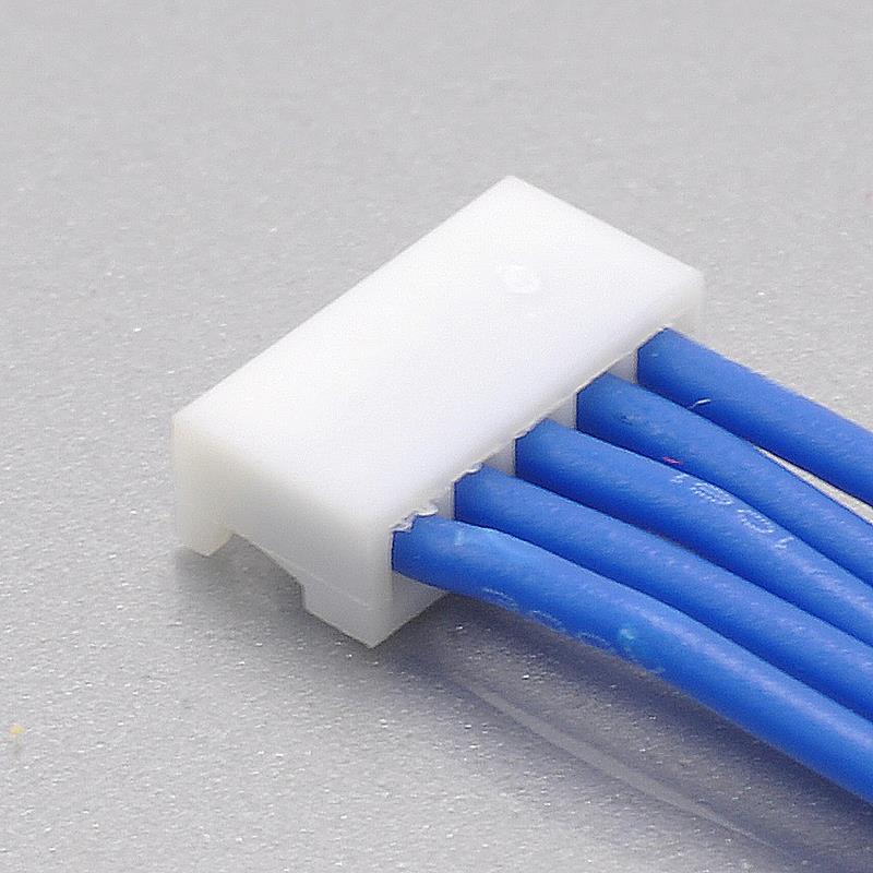
The crimp data — the part of the documentation a harness house actually needs
Here KONNRA publishes more detail than the Molex part datasheet, and it is the part worth passing straight to your harness supplier (PS-KR1252-01, clause 6.3):
- Conductor crimp width: 0.85±0.1mm
- Conductor crimp height: 0.50–0.60mm at AWG 28 · 0.45–0.55mm at AWG 30 · 0.40–0.50mm at AWG 32
- Insulation crimp width: 1.00mm maximum
- Insulation crimp height: 1.15mm max at AWG 28 · 1.05mm max at 30 · 0.85mm max at 32
- Minimum crimp strength: 1.36kgf at AWG 28 · 0.9kgf at 30 · 0.7kgf at 32
- Strip length: 1.1 to 1.5mm
- Terminal insertion force: 0.5kgf (4.9N) maximum
- Terminal-to-housing retention: 0.7kgf (6.86N) minimum
Molex publishes its crimp tooling and applicator data separately from the product specification, so the two documents are not directly comparable. On a board-in part, put the acceptance criteria above into the purchase order rather than leaving them to a harness house’s default — the crimp is the only compliant joint to the board, and it is also the only thing standing between a good assembly and a field failure.
One more process detail worth knowing, from the same specification: KONNRA lists a solderability test at 245±5°C for 3±0.5 seconds, requiring that 95% of the immersed area shows no voids or pin holes — a solderable-terminal test, even though the KR1252 bill of materials lists only a housing and a terminal. If your process depends on how the housing is fixed to the board, confirm it against the KR1252 engineering drawing rather than inferring it from the test schedule.
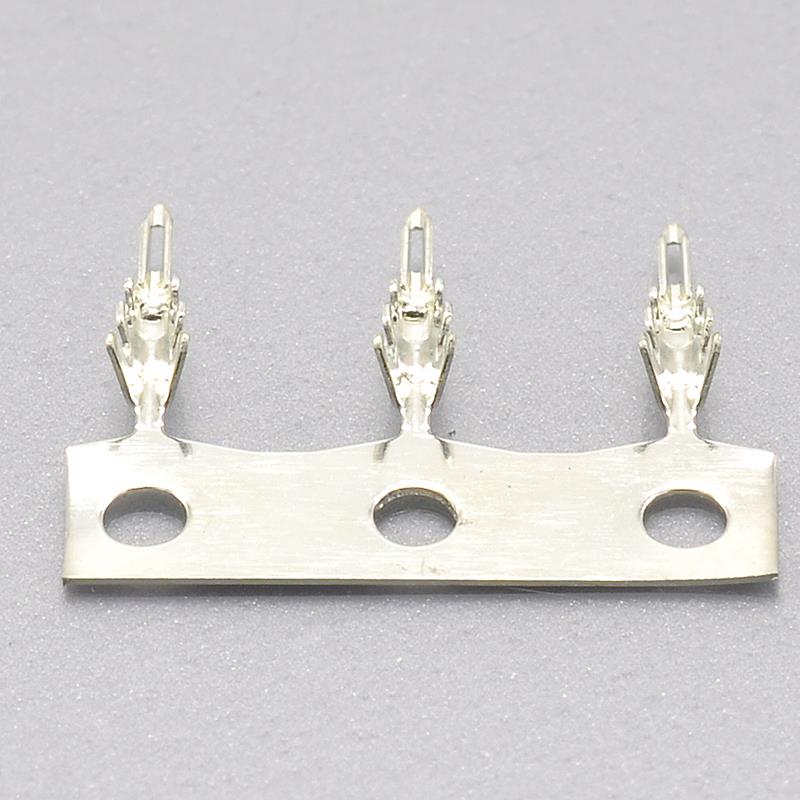
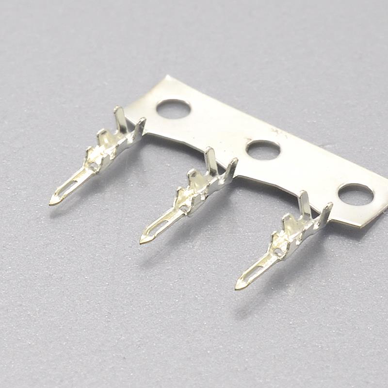
Where it fits — and what it is not for
Molex positions board-in as the connection type for designs needing a cost-effective, easy-to-assemble joint that does not need to be unmated on at least one end, and compares it against hand-soldering and against other board-in types, where it claims the widest range of pitch options, mating configurations and circuit sizes. KONNRA lists the KR1252 for computers, radio systems, automotive electronics and medical equipment.
That is broad, and the architecture narrows it. Board-in wins where the wire enters an assembly once and stays there.
Good fits: internal sub-assembly wiring in computers and peripherals, where a single-row 1.25mm housing keeps the footprint small and there is no header to place or solder · radio and communications boards, where a 1A signal interface at 125V covers internal signal and low-power runs · automotive electronics modules, in-cabin and under-dash, where the −40°C cold end is the relevant figure · medical equipment and instruments, supported by KONNRA’s ISO13485 medical device quality system where the product falls in that scope · sensor and lighting sub-boards where the harness is dressed once at build · appliances and small motorised products, where 1A per contact covers control and signalling at a low piece count · any board where a wafer would be the tallest or most fragile component — removing the header removes the tallest part of the interface and one solder joint · designs moving away from hand-soldered wire tails, which board-in replaces with a crimped, inspectable connection.
What it is not for. It is not a high-current connector: 1A per contact is a signal-and-low-power rating, and Molex’s own board-in terminal is additionally limited to 0.8A at AWG 32. It is not a repeatedly mated interface, because the architecture is designed so that at least one end stays put. And it is not a wire-to-board system — if you need a board header with a plug, you want the PicoBlade branch of the 1.25mm family.
One structural note that explains a common enquiry. Adapter harnesses are frequently requested on this interface, and the reason is structural rather than commercial: board-in, PicoBlade, CLIK-Mate and PanelMate all sit at 1.25mm pitch and share no housing, so when one board in a product uses a board-in housing and the other uses a plug-in 1.25mm interface, the transition has to happen inside the cable. Molex solves part of this itself with its pre-crimped leads — worth knowing if only one end is being re-sourced.
Engineer’s pre-release checklist
Run this before releasing a drawing for a 1.25mm board-in connector.
- Architecture confirmed. Board-in means the crimp housing mounts at the board and there is no wafer. If your drawing shows a board header plus a wire-side plug, you do not have a board-in design and KR1252 is the wrong family.
- Pitch measured, not assumed. 1.25mm covers board-in (51022), PicoBlade (51021 and its plug assemblies), CLIK-Mate (502380) and PanelMate (51146). None of them shares a housing.
- Position count confirmed against what each side actually documents — Molex 2 to 15 circuits by part number; KONNRA 2P to 16P.
- Voltage rating resolved in writing. KONNRA states 125V on the product page and both component pages and 50V in PS-KR1252-01 clause 4.0; Molex publishes 125V maximum for 50061. If your application runs above 50V, get the figure confirmed on the document your drawing will reference.
- Dielectric withstanding voltage confirmed as a test value, not a rating. 250V AC for 1 minute on both sides — and consistent here, unlike some other series in this catalogue.
- Current rating checked against your wire gauge. Molex documents 1.0A maximum per contact with 0.8A at AWG 32, plus a derating table by position count. KONNRA states 1A at 26 AWG with no derating table. Do not assume the headline figure applies at AWG 32 or at 16 positions.
- Wire gauge and insulation diameter inside the documented window — KONNRA documents AWG 26# to 32# with insulation 1.00mm max; Molex documents 0.50–1.00mm for 50061. Note the KONNRA product page row stating “Insulation O.D 1.25mm”, which matches the pitch and disagrees with the other three KONNRA sources.
- Operating temperature checked. Molex specifies −40° to +85°C; KONNRA specifies −40°C to +105°C, with its own heat-ageing test run at 105±2°C for 96 hours — so there is no published margin above the claim.
- Housing material checked against your process. Molex: Polyester. KONNRA: Nylon66 with UL94V-0. A polymer change is a process question if the housing sees reflow or a wash.
- Plating thickness confirmed in microns. Molex documents tin at 0.889µm minimum on the mating area and 0.914µm on the termination area. KONNRA documents tin over nickel with no thickness for either layer.
- Retention and strain relief designed, not assumed. Insertion force 0.5kgf (4.9N) max, retention 0.7kgf (6.86N) min, no latch. Specify the cable tie or twist tie location on the drawing.
- Crimp acceptance criteria passed to the harness house — crimp width 0.85±0.1mm, per-gauge conductor and insulation crimp heights, minimum crimp strength of 1.36 / 0.9 / 0.7 kgf at 28 / 30 / 32 AWG, strip length 1.1 to 1.5mm.
- Original part number status checked. Molex’s page for 50080-8000 lists the series as Obsolete; an older distributor snapshot still shows Active. Confirm the current status before freezing the reference.
- Mating durability confirmed if the housing will be re-loaded in service or rework — Molex publishes 30 cycles for tin-plated 1.25mm parts; KONNRA publishes no cycle count for KR1252.
- The terminal part number split confirmed. KONNRA’s specification lists two terminal part numbers (T12520PT0101A and T12520PT0102A), which is consistent with the two-wire-range split Molex uses — but the split is not stated. Ask which part number applies to 26 AWG and which to 32 AWG.
Getting a cross-reference check
Most MX1.25 board-in enquiries stall on the same thing: the buyer is not sure what information the supplier needs, so the enquiry never gets sent. The list is short.
- The original Molex part number, if you have it — a housing such as
51022-0200or51022-1500, or a terminal such as50061-8000or50080-8000 - Position count — Molex’s 51022 catalogue documents 2 to 15 circuits; KONNRA documents 2P to 16P
- Whether you need the housing only, the terminals only, or a loaded housing and a finished harness. The KR1252 bill of materials has no wafer, so the answer changes what you order
- Wire specification — gauge and insulation outside diameter. KONNRA documents AWG 26# to 32# with insulation 1.00mm max; Molex documents 0.50–1.00mm for 50061, so the jacket diameter is not optional information here
- Your load current, not just the connector rating. Close to 1A in a high-position-count housing means the derated value is the one your design has to satisfy
- Your circuit voltage, so the 125V-versus-50V question in KONNRA’s own documents can be resolved against your application rather than left open
- Operating temperature requirement — Molex’s housing is documented to +85°C and the KONNRA part to +105°C, and the difference matters in either direction
- Application and annual volume, so configuration, tooling and packaging can be matched to your programme
- A drawing or photo, if the part number is unreadable or the design has been reverse-engineered
When you send a part number, four things get confirmed against Molex’s own documentation: the position count, the wire gauge the terminal is validated for, the insulation diameter window, and the plating construction you need. Those four are where an MX1.25 board-in cross-reference most often goes wrong.
Connector lead time is typically 2–3 weeks, wiring harness lead time typically 3–4 weeks, and complete connector set samples can be delivered within 45 days, with key materials prestocked. On a board-in part, sample harnesses from the same process used in production are the more useful sample — because the crimp is the only compliant joint between the wire and the board, and that is the joint you are really qualifying.
Full technical write-up: Molex MX1.25 Board-In Connector Complete Guide
Disclosure: I work with KONNRA, which manufactures the KR1252 cross-reference to the Molex 1.25mm board-in system. The Molex board-in figures in this article are taken from Molex’s published part documentation for the 51022 crimp housing and the 50061 / 50080 terminals; the KONNRA figures are from KONNRA’s published KR1252 product documentation and specification PS-KR1252-01. Where the two sources disagree — or where one source contradicts itself — I have flagged the difference rather than averaged it, and where a parameter is not stated in the sources reviewed, I have said so instead of filling the gap.
https://konnra.com/molex-mx1-25-board-in-connector-complete-guide/
Dongguan Konnra Electronics Co., Ltd