Why “I need PicoBlade 1.25mm terminals” is an incomplete specification — and what to verify before you cross-reference the inline PicoBlade.
“I need PicoBlade 1.25mm terminals.”
It reads like a complete specification. It is not. If that is the whole line on a purchase order, there is roughly a one-in-two chance that the reel which arrives is one you cannot crimp — not because the supplier misread it, but because the Molex PicoBlade wire-to-wire system is built from two different families of crimp terminal, one for each half of the pair, and they are not interchangeable.
That fact sits at the centre of everything difficult about this connector, and it is the reason a wire-to-wire PicoBlade enquiry needs one extra piece of information before anything else can be quoted.
Here is the whole system — what it is, how the two halves differ, why its rating is four numbers rather than one, and the nine gaps to verify before you cross-reference it.
What the PicoBlade wire-to-wire system is
“Molex MX1.25 wire-to-wire” is trade shorthand for the Molex PicoBlade 1.25mm-pitch wire-to-wire connector system — the inline half of the PicoBlade family. Molex’s own document for it is Product Specification 510211009-PS, the tin-plated specification.
- Pitch: 1.25mm, single row
- Configuration: inline wire-to-wire, friction lock, polarised, two-point contact design
- Circuits: 2 to 15
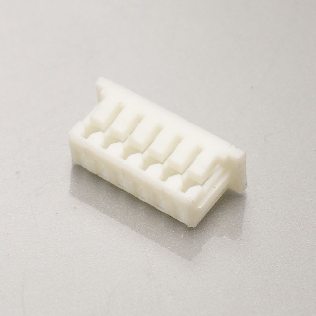
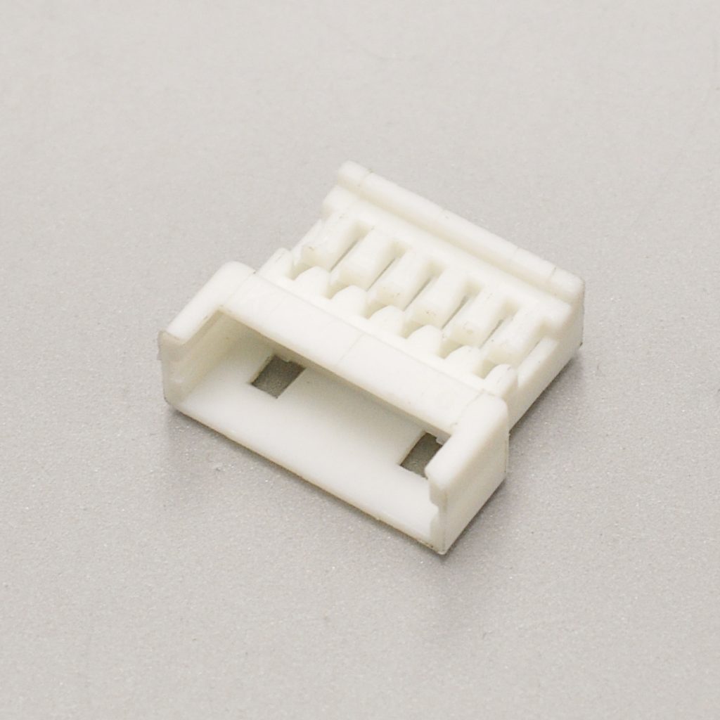
- Housing pair: 51021 receptacle housing mates with a 51047 plug housing — two different housing series
- Terminals, receptacle side: 50079 (AWG #26–28) · 50058 (AWG #28–32)
- Terminals, plug side: 50125 (AWG #26–28) · 50133 (AWG #28–32)
- Voltage rating: 125V AC (RMS)/DC
- Rated current: 2.0A at AWG #26 · 1.5A at AWG #28 · 1.0A at AWG #30 · 1.0A at AWG #32
- Applicable wire: AWG #26 to #32
- Insulation O.D.: φ0.5mm to φ1.04mm across all four terminals
- Contact resistance: 20mΩ max, with the crimped portion at 5mΩ max
- Insulation resistance: 100MΩ min
- Dielectric strength: 250V AC (RMS) for 1 minute
- Operating temperature: −40°C to +105°C, including terminal temperature rise
- Durability: 30 mating cycles (tin plating)
- Plug housing material: polyester, UL94V-0
- Standards: UL File E29179
- Panel mount: no
- Cross-reference equivalent: KONNRA KR1251
Molex positions the PicoBlade as ideal for space-constrained wire-to-wire and wire-to-board applications. It has held a mainstream position in compact consumer and industrial electronics long enough to function as a de facto standard for small inline wiring.
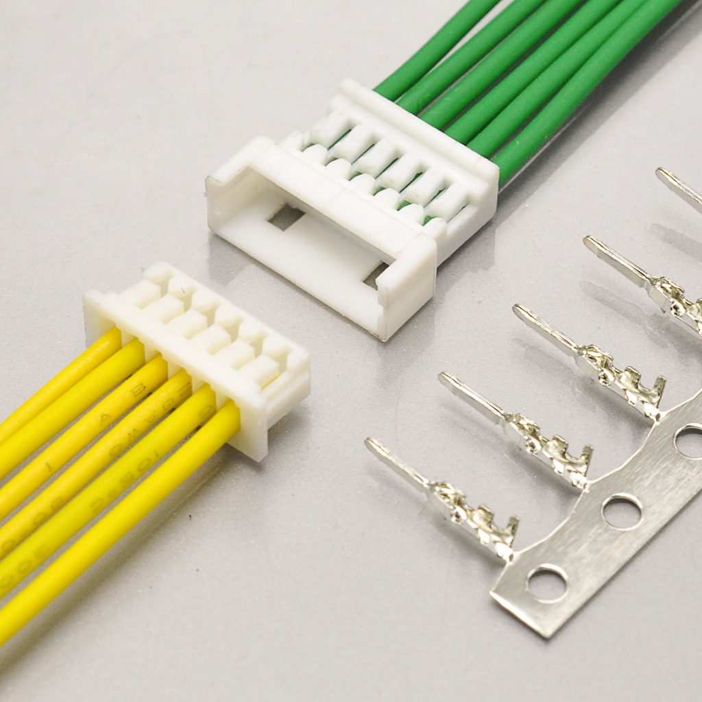
The two sides use different terminals
This is the single most important fact about the system, and the one that costs the most when it is missed.
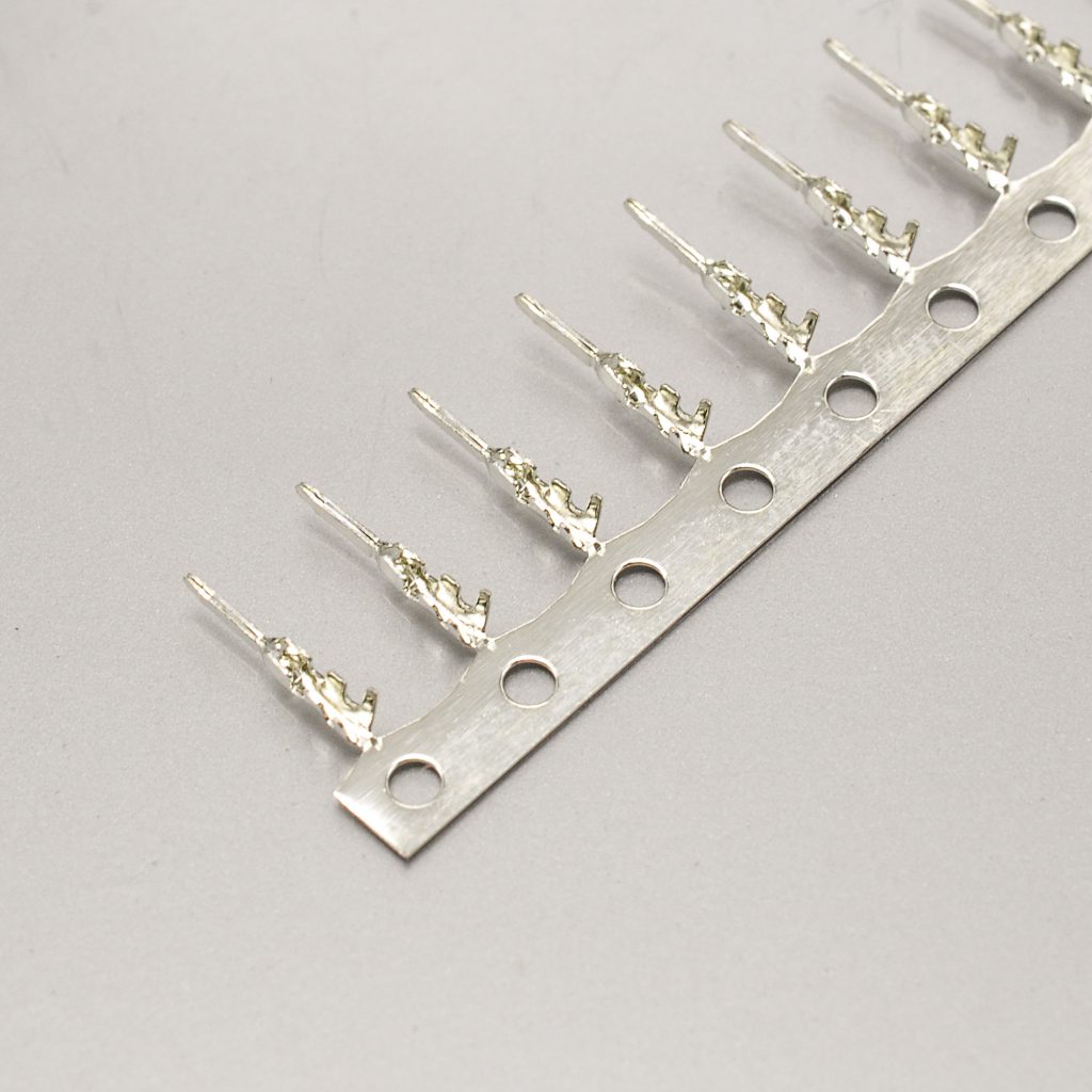
The receptacle side and the plug side use different crimp terminals. They are different part number families, they are not interchangeable, and one complete inline harness needs both:
- Receptacle side — 50079 series for AWG #26–28, 50058 series for AWG #28–32
- Plug side — 50125 series for AWG #26–28, 50133 series for AWG #28–32
The receptacle terminals are the same parts the wire-to-board PicoBlade uses. The plug terminals are unique to the inline system and exist for no other purpose. So “I need PicoBlade 1.25mm terminals” is an incomplete specification by construction.
How to specify it correctly, in two steps. First pick the pair that matches your wire gauge — then order both the receptacle and the plug version of that pair:
- Heavier wire, AWG #26–28 → 50079 receptacle + 50125 plug
- Finer wire, AWG #28–32 → 50058 receptacle + 50133 plug
AWG #28 is the overlap, and it is where harnesses go wrong. Both the 50079 and the 50058 are specified for AWG #28, and the same is true on the plug side — both the 50125 and the 50133 cover it. At AWG #28 the conductor gauge does not tell you which pair to order. Choose by what the rest of your harness uses: if any circuit runs at AWG #26 or #27 you are in the heavier family, and if any circuit runs at AWG #29 or finer you are in the lighter one.
One simplification. Insulation diameter is a single window across all four terminals on this system — φ0.5mm to φ1.04mm. That is simpler than the wire-to-board side, where the two terminal families carried different insulation maxima.
The current rating is four numbers, not one
Molex publishes the wire-to-wire rated current per wire gauge, and then a separate reference derating table by circuit count.
Level 1 — rated current by wire size. All four gauges share the insulation window of φ0.5mm to φ1.04mm:
- AWG #26 → 2.0A
- AWG #28 → 1.5A
- AWG #30 → 1.0A
- AWG #32 → 1.0A
Level 2 — reference derating by gauge and circuit count, at columns of 2 / 6 / 10 circuits:
- AWG #26 → 2.5A at 2 circuits · 2.0A at 6 circuits · 2.0A at 10 circuits
- AWG #28 → 2.0A · 1.5A · 1.5A
- AWG #30 → 1.5A · 1.0A · 1.0A
- AWG #32 → 1.3A · 1.0A · 1.0A
Molex’s stated conditions for that table matter as much as the numbers: the values are for reference only, the deratings are based on not exceeding a 30°C temperature rise, the rise is measured in the barrel area of the crimp terminal, the data is for all circuits powered, and PCB trace design can greatly affect temperature rise results. Molex also states that the sum of the current used on several circuits must not exceed the maximum allowable current, in addition to the per-circuit figure.
A caution about the derating columns. The wire-to-wire table uses 2, 6 and 10 circuits, while the wire-to-board table uses 2, 8 and 15. The two tables are not interchangeable — do not carry a wire-to-board derating figure across to an inline design, or the reverse.
Wire-to-wire versus wire-to-board at the same pitch
The two halves of the PicoBlade family share a pitch, a contact system and a housing standard — and they do not share a current rating. Molex publishes them as separate specifications, and KONNRA cross-references the inline half as KR1251 and the board half as KR1250.
- AWG #26 — wire-to-wire 2.0A versus wire-to-board 1.0A
- AWG #28 — 1.5A versus 1.0A
- AWG #30 — 1.0A on both
- AWG #32 — 1.0A versus 0.8A
Three things follow, and they matter more than the individual numbers.
The inline system is rated higher at the heavy end — twice as high at AWG #26. If your inline connection runs AWG #26, the wire-to-wire PicoBlade is a materially more capable connector than its board-mounted sibling, even though they are the same family at the same pitch. The usual assumption — that a cable joint is the weak link — is wrong on this family.
But the two are identical at AWG #30, and the wire-to-board side is lower at AWG #32. So there is no single “PicoBlade current rating”. The answer changes with the gauge and with which half of the family you are using.
And your harness takes the lowest rating in the chain. If a run goes from a board header, through a cable, to an inline joint and on to another board, the wire-to-board legs are the bottleneck at 1.0A — and a 2.0A inline joint in the middle of that run buys you nothing. Work out the limit from the weakest component, not the strongest.
Cross-referencing to the KONNRA KR1251
The KR1251 is documented as KONNRA’s equivalent to the PicoBlade 1.25mm wire-to-wire system.
Where the documents agree is worth stating, because on a cross-reference it is not a given: the pitch, the 125V rating, the two-point contact design, the friction lock with a mating lock, the 250V AC (RMS) one-minute dielectric withstanding voltage, the 100MΩ minimum insulation resistance, and the 20mΩ maximum contact resistance — with the crimped portion separately specified at 5mΩ max on both sides.
Where they differ. Nine points, in the order they tend to bite:
- Current rating — four numbers versus one. Molex rates 2.0A (AWG #26) · 1.5A (#28) · 1.0A (#30) · 1.0A (#32). KONNRA documents a flat 1A, which equals the two finer gauges and understates AWG #28 by a third and AWG #26 by half. The critical gauge is AWG #26: a 2-amp inline design risks being read as over-specification when in fact it sits inside the original part’s rating. State your gauge and current and have the figure confirmed for your design.
- The published wire range does not reach AWG #26. Molex covers AWG #26 to #32; the published KR1251 range is AWG #28 to #32. AWG #26 is exactly where this system’s advantage is concentrated — 2.0A against the wire-to-board half’s 1.0A — so if your inline joint uses #26, say so explicitly.
- The insulation window is one-sided on the KONNRA side. Molex specifies φ0.5mm to φ1.04mm — a two-sided window. KONNRA documents 1.0mm maximum with no minimum. A wire below 0.5mm is outside Molex’s specification, and the KR1251 documentation gives no lower bound at all.
- Mating durability is published by Molex and not by KONNRA. Molex specifies 30 cycles for the tin-plated version — a low figure for an inline joint a technician may separate to route a cable. Molex’s own force table shows withdrawal force on a 2-circuit connector falling from 2.8N at first mating to 1.8N by the 30th cycle. KONNRA publishes no cycle count for the KR1251.
- Plating. The Molex document reviewed here is the tin-plated specification, and Molex publishes a separate gold-plated specification for the same system. KONNRA documents tin over nickel, so the finishes line up on the tin route — but if your design assumed gold, confirm which specification applies.
- The component count is the biggest structural gap. Molex’s inline system is built from two housing series (51021 receptacle, 51047 plug) and four terminal part numbers (50079, 50058, 50125, 50133). KONNRA documents one housing and one terminal for KR1251. A wire-to-wire design needs to say which half of the pair it is buying — the receptacle side, the plug side, or a matched set.
- Housing material differs between the two halves. Molex lists the 51047 plug housing as polyester (UL94V-0, with a lock to the mating part and polarisation) and the 51021 receptacle housing as polyamide — and notes that the receptacle’s water absorption status can change the insertion and withdrawal force and weaken the click feeling of the lock when mating, without damaging the product’s function. KONNRA documents a combined PA66 / PBT / UL94 / Phosphor Bronze list for the series without splitting the halves. If your process or your customer’s specification names a material for a specific half, confirm which half it applies to.
- Circuit range. Molex’s wire-to-wire rated-current, derating and force tables run to 10 circuits — narrower than the wire-to-board tables, which run to 15. KONNRA documents KR1251 as 2 to 16 positions. Confirm the count you intend to order.
- Standards. Molex lists UL File E29179. KONNRA’s product documentation states RoHS compliance, with UL certification asserted at brand level. If your qualification requires UL recognised status specifically for this part, ask for the file reference.
Design cautions worth carrying into your review
Molex publishes an unusually detailed set of usage constraints for this system — nineteen numbered notes in the wire-to-wire specification. They are not marketing. They are the failure modes the product is known to have, and they are the most useful content in the document. KONNRA does not publish an equivalent list.
On electrical and mechanical limits:
- Do not mate or unmate under load. Molex states the product is not designed for mating and unmating under an active electrical circuit, and that doing so may cause a spark and product damage. An inline joint is exactly the kind a technician is tempted to open live — write the service procedure so that they do not.
- Respect the per-circuit rating, and the sum. The sum of the current across several circuits must not exceed the maximum allowable current, on top of the per-circuit figure.
- Tie the cable at least 50mm from the connector edge, with the tying force applied evenly across all wires. Molex defines that distance as a free length of wire — a length not subject to bias from a tie, a twist, or any bending that moves the wires out of their natural position. The wires must be dressed so the terminals float freely in the pocket. On an inline joint both ends can be pulled, so you need a tie at each end.
- No continuous pulling or stress force when mated — it can damage the contact area or the crimping.
- Do not hang loads on the connector, for example carrying a board by the harness while the connectors are engaged.
- After mating, do not let the boards apply pressure to the connector in the pitch direction, the span direction, or rotationally — Molex warns this can crack the solder or damage the connector.
On assembly and handling:
- Withdraw slowly, axially and straightly. Hold the wires together lightly and pull straight; angled or rough withdrawal can damage the connector.
- Mate along the mating axis. If diagonal mating is unavoidable, touch the external faces at under 10° and push from there.
- Use a new housing after extracting a terminal. Extracting a crimp terminal with a jig can deform the housing lance and, in Molex’s words, “reduce the terminal retention force enormously” after re-insertion.
- Protect the connector from external force and shock during harness assembly, packaging and transport, and keep clearance between the connector and the chassis so no pressure is applied.
- Do not wash the connectors. Molex states this may damage the product’s function.
- Fix wires and PCB to the chassis to avoid sympathetic vibration — sustained relative movement wears the contact area and causes contact defects.
- The applicable wire is, in principle, tin-plated copper stranded wire. Molex asks to be consulted and the wire evaluated in advance for anything else.
On appearance — these are explicitly not defects: black spots, bubbles or a different shade in the plastic parts, including discolouration from ageing; friction marks from the tin plating on the tail and nail; minor scratches on the housing surface and plating; and discolouration from ultraviolet exposure. Molex states none of these affect performance.
The 1.25mm class: where the inline PicoBlade sits
1.25mm is the most crowded pitch in the connector industry — three manufacturers, at least six systems, and no two of them mate.
- Molex PicoBlade wire-to-wire — W2W, 1.25mm, 2.0A (#26) / 1.5A (#28) / 1.0A (#30–32), 125V, AWG #26–32 → KONNRA KR1251
- Molex PicoBlade wire-to-board — W2B, 1.25mm, 1.0A (#26–30) / 0.8A (#32), 125V, AWG #26–32 → KR1250
- Molex PanelMate — W2B, 1.25mm, 1A, 125V → KR1253
- Hirose DF13 — W2B, 1.25mm, 1A, 150V → KR1256
- Hirose DF14 — W2B, 1.25mm, 1A, 150V → KR1255
- JST GH — W2B, 1.25mm, 1A, 50V AC/DC, AWG #30–26 → KR1259
- Molex Pico-EZmate — W2B, 1.20mm, 1.5A, 50V, AWG #28–30 → KR1200
- JST ACH — W2B, 1.2mm, 2A (1–3 circuits) / 1.5A (4–5 circuits), 50V AC/DC, AWG #32–28 → KR1201
Three things this settles. First, “1.25mm” identifies a pitch, not a connector, and not a connection type — six different systems sit at or near it, from three manufacturers. Second, a wire-to-wire option at this pitch is unusual: nearly every other system here is wire-to-board only, and the PicoBlade is the one where an inline joint and a board joint share the same receptacle housing (51021) and the same receptacle terminals (50058 / 50079) — so one contact system can be used at both ends of a run without doubling the qualification work. Third, the inline version is the more capable one: at 2.0A on AWG #26 it is rated twice its own wire-to-board sibling and twice JST’s GH series at the same pitch.
Engineer’s pre-release checklist
Run this before releasing a drawing for an inline PicoBlade-family connector.
- Connection type confirmed. The wire-to-board half is KR1250; the wire-to-wire half is KR1251. They share a pitch and a contact system and do not share a current rating.
- Both sides of the pair specified. Receptacle side uses 50079 / 50058; plug side uses 50125 / 50133. Two different families — one harness needs both.
- Wire gauge matched to the terminal family on each side, and AWG #26 confirmed in writing if you use it. Molex documents #26 to #32; the published KR1251 range is #28 to #32.
- Current checked per gauge, not per family — 2.0A (#26) · 1.5A (#28) · 1.0A (#30 and #32). The published KONNRA figure of 1A equals only the two finer gauges.
- The weakest link in the harness identified. A wire-to-board leg at 1.0A sets the limit for the whole run regardless of an inline joint rated 2.0A.
- Derating position established from your own board and your own tests. Molex’s values are reference only, based on a 30°C rise with all circuits powered, measured in the crimp barrel, and affected by PCB trace design. Use the wire-to-wire derating table, not the wire-to-board one — the columns differ (2/6/10 against 2/8/15).
- Sum of current across circuits checked against the maximum allowable, not just the per-circuit figure.
- Insulation outside diameter inside φ0.5mm to φ1.04mm — and note the KR1251 documentation publishes only a 1.0mm maximum, with no minimum.
- Mating durability considered — Molex specifies 30 cycles in the tin-plated version; KONNRA publishes no figure.
- Plating variant confirmed — the specification reviewed here is the tin-plated one. Confirm whether your design assumed gold.
- Housing material confirmed for the half you need — polyester on the 51047 plug side, polyamide on the 51021 receptacle side, with a stated water-absorption sensitivity that can change insertion force and soften the lock click.
- Cable tie placed at least 50mm from the connector edge on both sides, force applied evenly, so the terminals float freely in their pockets. This is the retention answer for a friction-lock inline joint.
- Retention sized against reality. Withdrawal force is 2.8N minimum at 2 circuits, falling to 1.8N by the 30th cycle. The friction lock is not a cable retention device.
- Service procedure checked for hot-mating — Molex states this product is not designed for mating or unmating under an active circuit.
- Terminal extraction procedure written — Molex advises fitting a new housing after extracting a terminal, because the lance deforms and retention drops sharply.
- Mating axis alignment in the build instruction — straight, or under 10° if diagonal mating is unavoidable.
- Wire construction confirmed as tin-plated copper stranded, or raised for evaluation if it is not.
- Panel-mount requirement checked. The PicoBlade wire-to-wire housing is not a panel-mount part; a bulkhead feed-through needs a separate arrangement.
- Board pressure checked after mating — Molex warns against pressure in the pitch direction, the span direction or rotationally, which can crack solder joints.
Getting a cross-reference check
Most wire-to-wire enquiries stall on the same thing: the buyer is not sure what information the supplier needs, so the enquiry never gets sent. On this system, one extra piece of information matters more than everything else.
- Which half of the pair you need — the 51021 receptacle side, the 51047 plug side, or a matched set. This is the question that most often decides between a correct and an incorrect quote.
- The original part number, if you have it — a housing such as
51021**00or51047**00, a receptacle terminal such as500798**00or500588**00, or a plug terminal such as501258**00or501338**00. - Wire gauge, and specifically whether it is AWG #26. Molex covers #26 to #32; the published KR1251 range is #28 to #32, so #26 needs to be raised explicitly.
- Insulation outside diameter — Molex specifies φ0.5mm to φ1.04mm; KONNRA documents a 1.0mm maximum with no minimum.
- Circuit count — Molex’s wire-to-wire tables run to 10 circuits; KONNRA documents 2 to 16.
- Plating finish required, including whether you assumed gold.
- Whether you need the connector only or a finished harness — and if a harness, the length and the far-end termination.
- Your load current, so the AWG #26 2.0A question and the derating position can be settled rather than assumed.
- Application and annual volume, so configuration, tooling and packaging can be matched to your programme.
- A drawing or photo, if the part number is unreadable or the design has been reverse-engineered.
When you send a part number, four things get confirmed against Molex’s own documentation: the side of the pair, the terminal family that matches your wire gauge, the housing series for the half you need, and the plating thickness you require. Those four are where an inline PicoBlade cross-reference most often goes wrong.
Connector lead time is typically 2–3 weeks, wiring harness lead time typically 3–4 weeks, and complete connector set samples can be delivered within 45 days. On an inline system a matched set matters: ask for both halves so the lock engagement and the click feel can be checked as a pair rather than as two loose parts.
Full technical write-up: Molex MX1.25 Wire-to-Wire Connector Guide
Disclosure: I work with KONNRA, which manufactures the KR1251 cross-reference to the Molex PicoBlade wire-to-wire system. The Molex figures in this article are taken from Molex’s published Product Specification 510211009-PS (wire-to-wire, tin plating); the KONNRA figures are from KONNRA’s published KR1251 documentation. Where the two disagree, I have flagged the difference rather than averaged it — and where a parameter is not stated in either document, I have said so instead of filling the gap.
https://konnra.com/molex-mx1-25-wire-to-wire-connector-complete-guide/
Dongguan Konnra Electronics Co., Ltd