Peak demand management is a narrower objective than cost reduction generally, and it is the one storage addresses most directly. The system supplies the difference between site demand and a chosen threshold, for as long as each excursion lasts, and the billed maximum falls accordingly. What decides whether it performs is the threshold and the ratio behind it. MPMC POWERTECH CORP., established in 2008 and headquartered in Shanghai Pudong, publishes a stationary HBD-A range from 125 kW and 261 kWh upward.
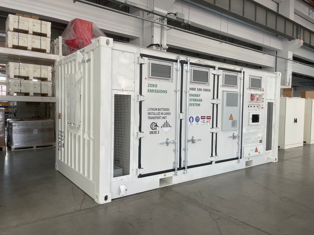
MPMC HBD-A Series battery energy storage system — HBD-500-1000
The Threshold Is an Economic Decision
A lower threshold captures more saving but requires a larger system that cycles harder; a higher one costs less to install and saves less. Neither is correct in the abstract, and the point where additional capacity stops adding return is specific to the site’s own demand pattern.
A fifteen-minute interval profile across a full billing cycle shows how much energy sits above any candidate threshold and how often each excursion occurs. Modelling two or three candidates against that profile identifies the crossover point, which a single peak figure cannot show.
Sharp Excursions and Long Plateaus Need Different Systems
The profile also identifies the duty shape. Brief sharp peaks are power-led: the system must supply a large difference for a short period. Long afternoon plateaus are energy-led: a smaller difference sustained for hours.
MPMC’s published range makes that selectable. The HBD-250-1000 and HBD-500-1000 both hold 1,045 kWh at 250 kW and 500 kW respectively, and the HBD-1000-2000 is listed at 1,125 kW with 2,170 kWh. That the same stored energy appears at two power ratings is the clearest signal that duty shape rather than capacity selects the model.
What the Profile Should Tell You
|
What to extract |
Why it governs the design |
What it selects |
|
Peak magnitude above threshold |
Sets the power the system must supply |
Rated AC power required |
|
Duration of each excursion |
Sets the energy drawn per event |
Capacity required per event |
|
Frequency of excursions |
Determines cycles per day |
Which warranty limit binds first |
|
Coincidence with tariff periods |
Affects whether arbitrage adds value |
Whether a second purpose is worth pursuing |
|
Largest motor starting event |
May exceed the shaving requirement |
Overload capability needed |
|
Seasonal variation |
The worst month governs, not the average |
Sizing basis for the whole year |
Losses and Degradation in the Saving Model
Energy stored is not energy returned. Conversion losses apply in both directions, depth of discharge limits how much of the pack is used since MPMC rates cycle life at 90%, and ambient derating applies above 45°C. A model built on nameplate capacity will overstate the reduction achieved.
Capacity also changes with use. MPMC lists 8,000 cycles at 90% depth of discharge for the HBD-A series with published end-of-life retention of at least 70%, so the peak reduction achieved in year eight differs from year one. Modelling against end-of-life capacity is what makes the payback figure defensible over the contract term.
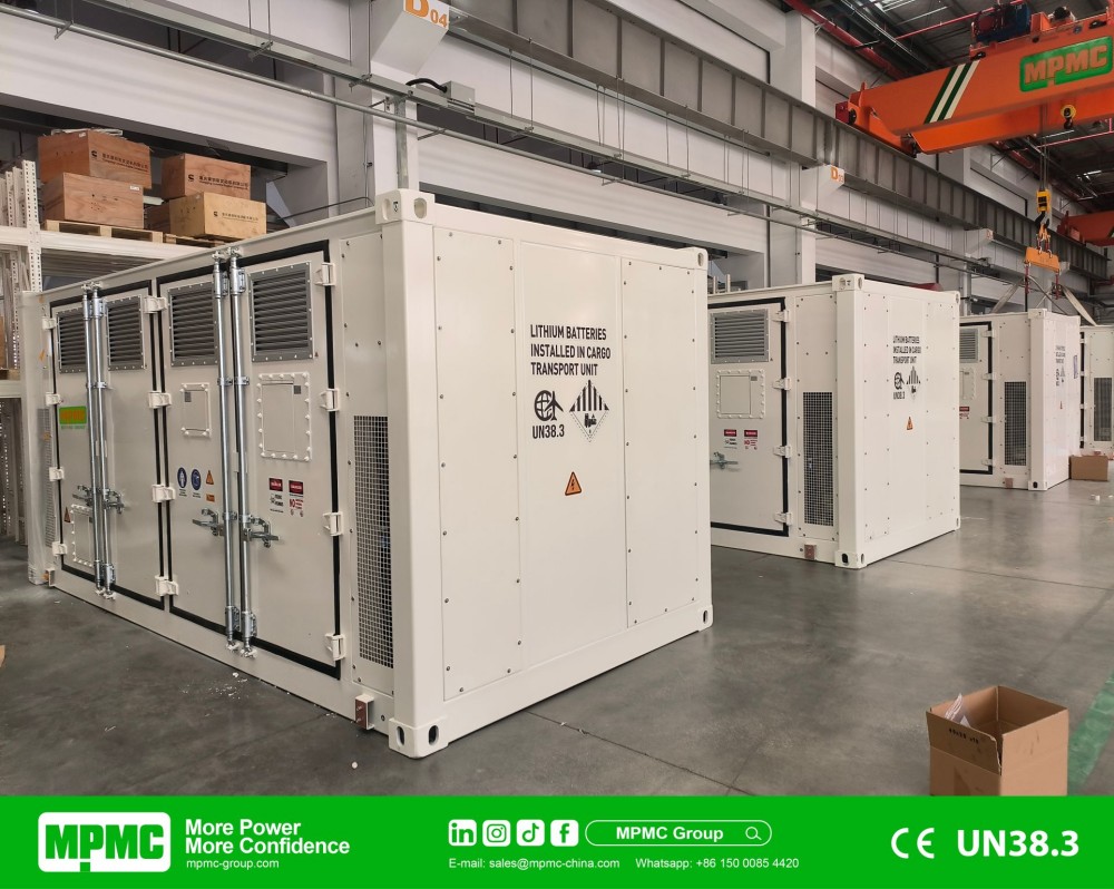
MPMC HBD-500-1000 battery energy storage systems — 10-unit installation
Where the Warranty Meets the Operating Strategy
MPMC’s published warranty for the HBD-A series is 5 years or 2.2 MWh per kWh of capacity for the system and 10 years or 4.3 MWh per kWh for battery performance, with a validity condition requiring battery box temperature between 0°C and 25°C with a ±3°C tolerance and humidity at or below 80%.
A site shaving aggressively reaches the throughput allowance before the calendar term, which means the strategy that maximises annual saving and the one that maximises covered life are not identical. Deciding which the project is optimising for, and confirming that the cooling design satisfies the temperature condition, belongs in the specification.
Platform Specification and Siting
MPMC lists 314 Ah LFP cells across the HBD-A series with liquid cooling, IP54 system and IP67 battery pack protection, aerosol fire suppression to CE, an operating range of −20°C to +55°C with derating above 45°C and a maximum altitude of 3,000 m, with off-gas detection and a water spray inlet on larger units.
Siting the system inside or adjacent to a working facility brings the fire strategy into scope earlier than the electrical design does. Separation distances, detection interfaces with the building system and emergency access are determined locally and should be settled with the authority having jurisdiction before the position is fixed.
Documented Peak Management Installations
MPMC lists a Netherlands peak-shaving installation totalling 3.2 MWh using 125 kW / 260 kWh and 100 kW / 200 kWh configurations, and a 4.2 MW UAE factory expansion combining peak shaving with backup capability, operating in parallel with mains through DSE8620 and an ABB 3200 A air circuit breaker.
These describe the class of installation delivered rather than a saving forecast for a different tariff or demand pattern, which is why the modelling has to run on the site’s own interval data.
Where the Site Load Is Expected to Change
A demand profile rarely holds still. A new production line, extended shifts or an electrified vehicle operation all move the shape the system was sized against, and a scheme designed only for today can find itself shaving the wrong peak within a few years.
Expansion at this scale happens by adding units in parallel, which preserves the certified baseline and keeps spares common. What makes it straightforward is reserving switchgear capacity, control configuration and physical space in the first phase, so stating the eventual target at enquiry rather than only the immediate requirement is worth doing.
Peak Management Project Checks
● Supply a fifteen-minute interval profile across a full billing cycle.
● Model two or three candidate thresholds rather than assuming one.
● Extract peak magnitude, excursion duration and frequency separately from the profile.
● Select on the ratio of rated power to capacity, not on capacity alone.
● Check overload capability against the largest motor starting event.
● Include conversion losses, depth of discharge and derating in the saving model.
● Model the reduction against end-of-life capacity rather than first-year capacity.
● Confirm the cooling design satisfies the battery temperature condition.
https://www.mpmc-group.com/
MPMC Powertech Corp.