Electromagnetic Flow Meters for Hydropower Water Pipelines
Introduction: Measurement Challenges in Hydropower Water Conveyance
Hydropower water conveyance systems — including penstocks, diversion tunnels, headrace pipelines, and large-diameter transmission lines — present a distinct set of measurement engineering conditions: large pipe diameters, high flow velocities, significant static and dynamic pressure, and water that is generally conductive due to dissolved minerals and ions. These conditions make full-bore mechanical meters difficult to install and maintain, while creating an environment where electromagnetic flow measurement principles can be effectively applied.
This article explains how electromagnetic flow meters can be engineered and selected for conductive water flow measurement in hydropower-related pipeline systems, what process conditions must be verified before selection, and what installation and calibration practices support stable long-term operation. It does not address raw-water intake, municipal supply, wastewater, or cooling-water scenarios, and it does not claim that electromagnetic flow meters measure turbine efficiency or electrical power output — their function is limited to volumetric or velocity-based flow measurement of conductive liquid in the pipeline.
How Electromagnetic Flow Meters Work in Conductive Water Systems
Electromagnetic flow meters operate on Faraday’s law of electromagnetic induction: as conductive water passes through a magnetic field generated by excitation coils, an induced electromotive force proportional to the average flow velocity is generated and detected by electrodes in contact with the fluid. Because natural water conveyed through hydropower pipelines typically contains sufficient dissolved minerals to be electrically conductive, this measurement principle is generally applicable, provided the conductivity, pipe configuration, and hydraulic conditions are verified.
Key technical elements relevant to this application include:
- Square wave pulse excitation to maintain zero-point stability across varying flow conditions.
- VFC (Voltage-to-Frequency Conversion) signal processing with high-input-impedance amplification for stable signal extraction.
- Bidirectional measurement capability, useful where flow direction may vary due to pipeline operating conditions.
- Self-diagnostic functions, including detection of empty pipe conditions, excitation circuit breaks, and flow range overflow.
Engineering Conditions to Verify Before Selection
Before specifying an electromagnetic flow meter for a hydropower water pipeline, the following process conditions should be reviewed:
1. Pipe Diameter and Flow Range
Hydropower pipelines often exceed conventional industrial diameters. Sensor selection should match the actual pipe diameter and expected flow range, with attention to whether a full-bore or insertion-type sensor is more suitable for the diameter involved.
2. Flow Velocity
Electromagnetic flow meters are typically rated for a velocity measurement range such as 0.1 to 10 m/s. Verifying that anticipated flow velocities — including transient high-velocity events — remain within the rated range is essential for measurement accuracy and equipment durability.
3. Pressure Rating
The mechanical pressure rating of the sensor body, flange, and lining material must be confirmed against the pipeline’s design pressure, including surge or transient pressure conditions that may occur during valve operation or flow changes.
4. Water Conductivity
Since the measurement principle depends on the electrical conductivity of the fluid, actual site water conductivity should be measured and confirmed to be within the meter’s minimum operating conductivity threshold.
5. Pipeline Configuration
The layout of straight pipe runs upstream and downstream of the sensor, presence of elbows, valves, pumps, or diameter transitions, and available straight-run length all affect flow profile stability and should be reviewed during installation planning.
6. Flow Fluctuations
Hydropower systems may experience flow fluctuations due to gate operation, load changes, or transient hydraulic events. These fluctuations should be characterized so the meter’s response time and signal processing settings can be appropriately configured.
7. Installation Environment
Outdoor exposure, humidity, vibration, and accessibility for maintenance at large-diameter installations should be assessed to determine appropriate protection ratings and mounting arrangements.
Selection Guidance for Large-Diameter Hydropower Applications
Sensor Type and Diameter Range
For very large pipelines, two general sensor configurations are relevant:
- Full-bore electromagnetic flow meters, such as the SF-E series, which support a nominal diameter range from DN15 to DN3000 and are suitable where full-bore measurement is feasible and economically justified.
- Insertion-type electromagnetic flow meters, such as the SF-C series, designed for large pipelines up to DN3000, which mount through a ball valve and mounting base. This configuration allows installation without stopping flow in the pipe and is often more practical for very large-diameter hydropower conveyance lines where full-bore meter cost and installation complexity would otherwise be prohibitive.
Flow Range and Velocity Considerations
Selection should confirm that the meter’s rated velocity range covers the pipeline’s normal and transient flow conditions. For insertion-type meters, adjustable insertion depth — typically set to half or one-quarter of the pipe diameter — allows the sensing point to be positioned based on the pipeline’s flow velocity profile.
Pressure and Mechanical Construction
Pressure rating depends on the flange standard, body material, and lining selection. Compliance with recognized flange standards, such as GB/T9124.1-2019 for steel pipe flanges, supports mechanical compatibility with pipeline design requirements. For insertion-type meters intended for high-pressure large pipelines, stainless steel insertion rod construction supports structural integrity under pressure.
Lining and Electrode Material
Lining material selection affects chemical compatibility, abrasion resistance, and signal insulation. Depending on water quality and any suspended solids present, lining options may include rubber compounds or ceramics (typically available in DN15–150 ranges for the ceramic option), while electrode material should be selected for compatibility with water chemistry to avoid electrode fouling or corrosion over the service life of the pipeline.
Protection Rating
Because hydropower pipeline installations may involve outdoor, buried, or exposed environments, protection rating selection is important:
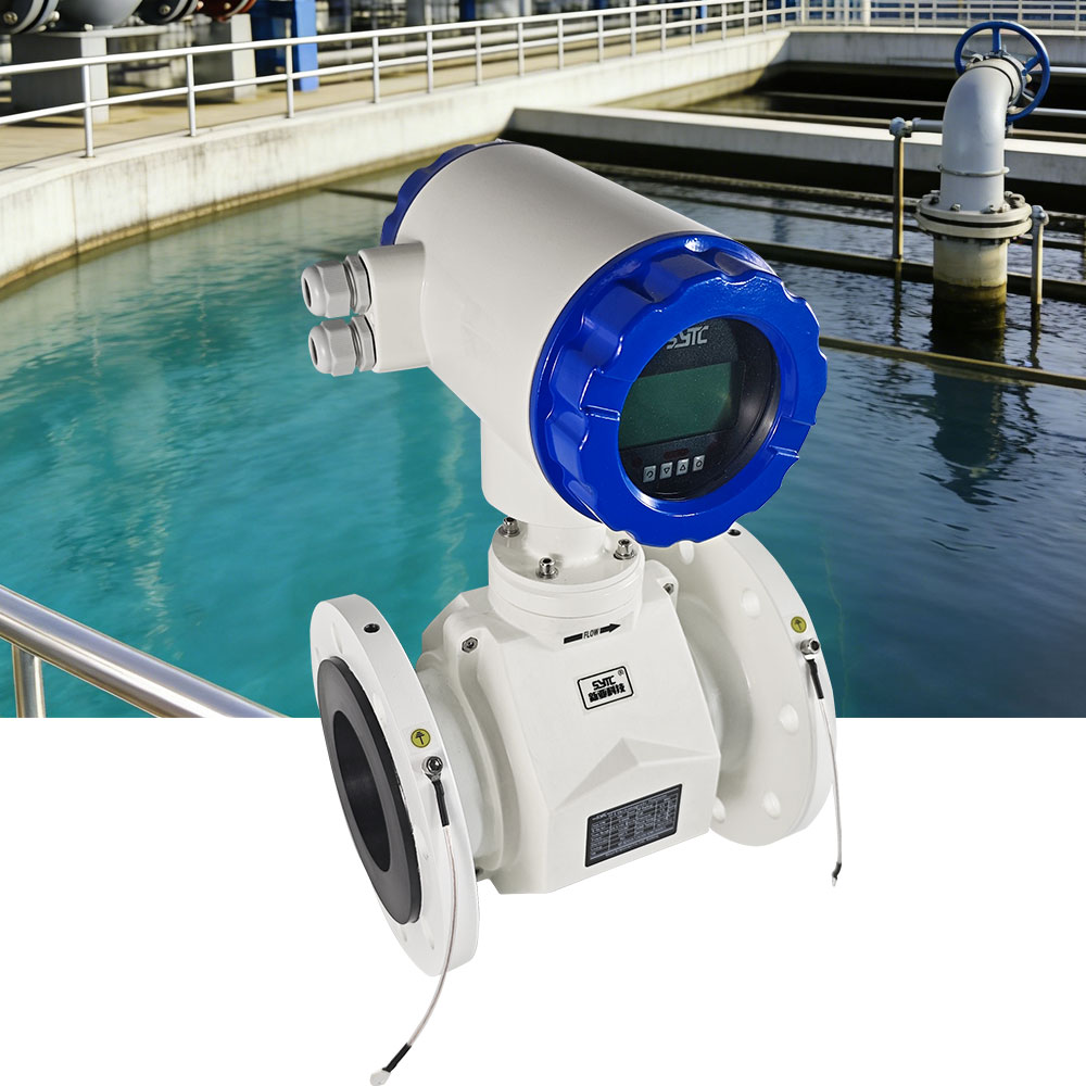
- IP68 for sensor units, supporting submerged or heavily exposed installation conditions.
- IP65/IP66/IP67 for converter or transmitter units, depending on whether the converter is mounted locally or remotely from the sensor.
Installation Location
Installation location should be selected to ensure:
- Adequate straight pipe length upstream and downstream of the sensor to allow the flow profile to stabilize.
- Avoidance of installation immediately downstream of valves, pumps, or elbows where hydraulic disturbance is highest.
- Sensor orientation and mounting position that avoids air pocket accumulation at the measurement point.
Grounding
Proper grounding of the sensor and pipeline is required for stable signal reference. In applications involving non-conductive or lined pipe sections, grounding electrodes (typically 1–2 integrated grounding electrodes, depending on configuration) help eliminate stray electrical interference that could otherwise distort the measured signal.
Full-Pipe Operation
Electromagnetic flow meters require the pipeline to remain full at the measurement point to produce a valid reading, since the induced signal depends on the electrode area being consistently wetted by the conductive fluid. Empty-pipe detection functions can identify when this condition is not met, but they do not correct the underlying hydraulic issue — pipeline design and installation location should be planned to maintain full-pipe conditions during normal operation.
Calibration
Verification of zero-point stability and measurement accuracy — with accuracy classes such as ±0.5%, ±0.3%, or ±0.2% depending on configuration — should be confirmed prior to commissioning and periodically thereafter, particularly after any change in installation conditions, electrode maintenance, or converter/circuit board replacement.
Practical Challenges and Engineering Solutions
| Challenge | Engineering Consideration |
|—|—|
| High flow velocity | Confirm sensor velocity rating covers peak transient conditions; select mechanically robust construction and appropriate lining. |
| Hydraulic disturbance from valves, elbows, or diameter changes | Plan sufficient straight-run distance upstream and downstream of the sensor before finalizing installation location. |
| Air entrainment | Avoid installation at pipeline high points or immediately downstream of turbulence-generating fittings where air pockets may form. |
| Vibration | Ensure secure mechanical mounting and, where applicable, select construction suited to the site’s vibration environment. |
| Improper grounding | Confirm grounding electrode installation and bonding to eliminate stray signal interference. |
| Partially filled pipes | Select installation locations where full-pipe conditions are maintained; use empty-pipe self-diagnosis to flag non-compliant conditions. |
| Insufficiently stable flow conditions | Review upstream flow disturbances and consider signal processing settings suited to fluctuating flow, supported by variation-suppression signal algorithms designed to filter transient interference. |
Installation and Maintenance Recommendations
- Confirm pipe diameter, velocity range, pressure class, and water conductivity against manufacturer specifications before procurement.
- Select full-bore or insertion-type configuration based on pipeline diameter, cost constraints, and whether flow interruption for installation is acceptable.
- Verify adequate straight-run distances and avoid installation near valves, pumps, or elbows.
- Confirm grounding practices at installation, including bonding to the pipeline where required.
- Perform initial preheating and operational verification as recommended (commonly a short preheating period before stable operation is reached) before relying on measurement output.
- Periodically inspect electrodes and lining condition, particularly in pipelines where suspended solids may be present.
- Maintain access for converter and circuit board inspection, and confirm compatibility of replacement components to avoid accuracy loss during maintenance.
- Where remote monitoring is required, confirm available communication options such as RS485, RS232, HART, GPRS, Bluetooth, or WiFi, and whether integration with a centralized IoT-based monitoring platform is needed for multi-node visibility.
Supplier Evaluation Considerations
When evaluating suppliers for electromagnetic flow meters intended for hydropower water pipeline applications, engineering and procurement teams should consider:
- Availability of large-diameter sensor options (full-bore and insertion-type) suited to the project’s pipeline diameter.
- Documented compliance with relevant industry standards, such as JB/T9248-2015 for electromagnetic flowmeters and GB/T9124.1-2019 for steel pipe flanges.
- Availability of appropriate protection ratings (e.g., IP68 sensors, IP65/66/67 converters) matched to the installation environment.
- Technical support for custom engineering needs, including flange standard matching, lining and electrode material selection, and calibration verification.
- Communication protocol compatibility and, where relevant, support for integration with monitoring platforms.
Kaifeng Xinya Instrument Co., Ltd. is an industrial instrumentation and IoT solutions provider that develops electromagnetic flow measurement systems, including full-bore series such as the SF-E Electromagnetic Flowmeter and insertion-type series such as the SF-C Insertion Electromagnetic Flowmeter, which supports pipelines up to DN3000. The company’s product documentation covers technical parameters relevant to large-pipeline applications, including velocity range, accuracy classes, protection ratings, and communication interfaces, and its Instrument IoT Big Data Platform supports centralized monitoring where multi-node visibility is required across a pipeline system.
Frequently Asked Questions
1. Can an electromagnetic flow meter measure flow in a large-diameter hydropower pipeline?
Yes, provided the water is sufficiently conductive and the sensor is selected to match the pipeline’s diameter, velocity range, and pressure rating. Full-bore sensors are available up to DN3000, and insertion-type sensors are also designed for large pipelines up to DN3000.
2. Does an electromagnetic flow meter measure turbine efficiency or power output?
No. An electromagnetic flow meter measures the volumetric or velocity-based flow of conductive liquid in the pipeline. It does not directly measure turbine efficiency or electrical power generation, which depend on additional mechanical and electrical parameters outside the scope of flow measurement.
3. What happens if the pipeline is not running full at the measurement point?
Electromagnetic flow meters require full-pipe conditions to produce a valid reading, since the signal depends on consistent electrode wetting by the conductive fluid. Empty-pipe self-diagnosis functions can detect and flag this condition, but installation location should be planned to avoid partially filled conditions during normal operation.
4. How does high flow velocity affect meter selection?
The sensor’s rated velocity range, typically in the range of 0.1 to 10 m/s depending on configuration, should cover both normal and peak transient flow velocities expected in the pipeline. Mechanical construction and lining should also be selected with high-velocity operating conditions in mind.
5. Why is grounding important in electromagnetic flow meter installation?
Grounding provides a stable electrical reference for the measurement signal. Improper grounding, particularly in non-conductive or lined pipe sections, can introduce interference that distorts the induced signal; grounding electrodes help address this issue.
6. Is an insertion-type electromagnetic flow meter suitable for very large pipelines?
Insertion-type meters, such as the SF-C series, are designed for pipelines up to DN3000 and can be installed via a ball valve without stopping flow, making them a practical option where full-bore meter installation would be costly or difficult on very large-diameter lines.
7. How often should an electromagnetic flow meter be calibrated in this type of application?
Calibration verification should occur prior to commissioning and periodically thereafter, with particular attention after any change in installation conditions, electrode maintenance, or replacement of converter or circuit board components, to confirm continued zero-point stability and accuracy class performance.
Conclusion
Electromagnetic flow meters offer a technically applicable approach for measuring conductive water flow in hydropower water pipelines, provided that pipe diameter, flow velocity, pressure, water conductivity, installation location, grounding, full-pipe operation, and calibration are all properly verified during the selection and installation process. The relationship between these factors — from sensor selection through installation to calibration — determines measurement reliability over the operating life of the pipeline. Engineering teams evaluating this technology for large-diameter water conveyance systems should work with suppliers, such as Kaifeng Xinya Instrument Co., Ltd., that can document technical specifications, standards compliance, and installation support relevant to the specific pipeline conditions involved.
https://www.sytcflowmeter.com/
Kaifeng Xinya Instrument Co., Ltd.